Your 555 does not produce a squarewave, it is a rectangular wave because its capacitor charges from two series resistors but discharges from only one resistor. Then the integrated waveform is a sawtooth, not a triangle.
The first opamp (fed from the 555) is useless.
The lousy old 324 opamp has a poor high frequency response that cannot produce the harmonics of a triangle wave. The simulation software might not know it.
So far, it doesn't look like you've "made" anything, you've only simulated something. Which simulator are you using. Look at the circle data points in the blue "triangle data". They appear to be making a sine wave. Did your simulator just cram the triangle wave into fit the pattern of data points? Is your 555 signal higher frequency than the iteration steps of simulator? Try bumping up the frequency (shortening the interval) of the simulator's steps.
Your latest "triangle" leans to the left side because the "squarewave" is not perfectly square.
A CD4047 IC has an RC oscillator driving a divide-by-two so its outputs are a perfect square.
Here is yours:
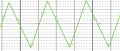
The DC level of your output waveform increases until the U15A output begins to clip. This is because there is no feedback from the integrator output to the comparator input.
As in post #5, there is a very common 2-opamp circuit that produces both a square wave and triangle wave. It will do everything you say you want with 2 sections of an LM324. You can then use a third LM324 section to buffer the triangle signal after it has been adjusted for amplitude and output voltage range. Note that the output quality will be low (small non-linearities, crossover distortion, etc.) due to the low performance LM324.
I've tried various triangle wave circuits over the years and this version is by far the best. Be careful if you use this with your LM358 with its cross-over distortion, you'll get a weird glitch at the inversion of each triangle point.
With a bit of manipulation of the pgnd voltage on U2, and R2 and R3 it should be possible to output a 0.4V to 2V triangle that the TS originally wanted. A rail-to-rail output op-amp would make the maths easier!
NOTE: this circuit posted immediately above by LowQcab DOES NOT produce a triangle wave. It is simply a wave that charges and discharges a capacitor without constant current control. It looks more like a shark-fin (almost a triangle). If that is good enough for your application, fine. If not, use an appropriate circuit.
A true triangle wave is produced by the circuit posted by @crutschow
True, it's High-Impedance, and not perfectly symmetrical,
but the "area-under-curve" is precisely the same as a proper "perfect" Triangle-Wave,
so it's well suited to PWM applications.
Its usefulness depends on what is meant by ....... ""......make the triangular wave that feed modulation input of driver. ""
It's just an option, and it's a very simply and easy one.
.
.
.
The fist circuit in post #1 produced 550Hz.
The second circuit in post #6 produced 98Hz.
The third circuit in post #12 produces 2kHz.
Why does the circuit in post #16 produce ultrasonic 32.5kHz?
The fist circuit in post #1 produced 550Hz.
The second circuit in post #6 produced 98Hz.
The third circuit in post #12 produces 2kHz.
Why does the circuit in post #16 produce ultrasonic 32.5kHz?
If You will expand the Picture You will find the formula for
the Frequency generated by the Circuit on page 16.
The Capacitance is calculated in Farads.
The shown values were from a different project.
.
.
.
 Facebook
 Google
 GitHub
 Linkedin