Hi All,
First of all I want to start by thanking you all in advance for replies!
I have a circuit using a 555 setup in a monostable configuration. Now, this is set up so that the output voltage goes high when the power to the circuit is switched on.
It then remains high for 10 seconds, and then goes low.
Now, I have tested the output with a resistor LED combination, to make my LED light up after the 10 second period.
I now want to power a whole (simple) circuit, rather than just an LED.

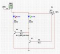
The diagram shows how my simple circuit is setup. Note that the input voltage labelled 12V varies between 0V and 12V to alternate which LED is actually on. This input voltage will come from an external sensor.
I then though that I could power this circuit via the output of the 555 Timer, i.e. due to the fact that the output of the timer goes low after 10 seconds, connect this output to where on the image it shows the transistors are grounded. Now, connected the +V rail to +Volts would therefore mean that the circuit would only switch on when the output of the 555 is low because of the fact that when the output is high, there would be a potential of approximately 0V across the emitter and collector of the transistors.
I am not really sure if my way of thinking is correct, and I would appreciate your guidance and advice!
Thanks again,
Regards,
Paw
First of all I want to start by thanking you all in advance for replies!
I have a circuit using a 555 setup in a monostable configuration. Now, this is set up so that the output voltage goes high when the power to the circuit is switched on.
It then remains high for 10 seconds, and then goes low.
Now, I have tested the output with a resistor LED combination, to make my LED light up after the 10 second period.
I now want to power a whole (simple) circuit, rather than just an LED.
The diagram shows how my simple circuit is setup. Note that the input voltage labelled 12V varies between 0V and 12V to alternate which LED is actually on. This input voltage will come from an external sensor.
I then though that I could power this circuit via the output of the 555 Timer, i.e. due to the fact that the output of the timer goes low after 10 seconds, connect this output to where on the image it shows the transistors are grounded. Now, connected the +V rail to +Volts would therefore mean that the circuit would only switch on when the output of the 555 is low because of the fact that when the output is high, there would be a potential of approximately 0V across the emitter and collector of the transistors.
I am not really sure if my way of thinking is correct, and I would appreciate your guidance and advice!
Thanks again,
Regards,
Paw
Last edited: