Digital isolation drive circuit,Marx high voltage pulsed generator

Thread Starter

Mahir98

Joined Nov 8, 2024
5
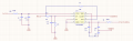
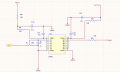
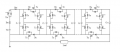
At present, I need to develop a Marx type high-voltage pulse generator with adjustable pulse voltage of 1-30kV, frequency of 100-1000Hz and pulse width of 1-10us. At present, part of the main circuit is planned to adopt traditional Marx circuit, and the signal sending module uses FPGA. In order not to have the same circuit structure as others. Plan to isolate the circuit and drive the circuit, take the digital isolation drive way, hope that after seeing the problem, can help me answer questions, please!
 

DickCappels

Joined Aug 21, 2008
10,661
Mahir98 wrote: "...can help me answer questions, please!"
It depends on the question!

There are plenty highly skilled electronics people here, so you will probably get good answers. Please if more than one question (not related to a pervious question) should have its own clean thread.
 

Thread Starter

Mahir98

Joined Nov 8, 2024
5
This is the digital isolation circuit and driver circuit that I designed. The digital isolation circuit receives signals from the FPGA. The driving signal has a frequency range of approximately 100-1000 Hz and a pulse width of 1-10 us. The driver circuit outputs to the solid-state switch on the Marx circuit to control the signal within the desired range. Additionally, this isolation circuit and driver circuit can also achieve fast simultaneous response between switches, preventing the entire breakdown phenomenon from occurring.
 

Attachments

Thread Starter

Mahir98

Joined Nov 8, 2024
5
Mahir98 wrote: "...can help me answer questions, please!"
It depends on the question!

There are plenty highly skilled electronics people here, so you will probably get good answers. Please if more than one question (not related to a pervious question) should have its own clean thread.
can you answer my question?
 

MisterBill2

Joined Jan 23, 2018
27,180
I am not familiar with the MARX circuit, do you have an example of one that you can share with us??
What I believe I see is a classic full wave voltage adder circuit/charge pump, with all of the diodes replaced by mosfets, with none of the control system portion shown.

That circuit can sort of work if it does not suffer a voltage breakdown.
Really, this looks a lot like a schoolwork problem that I would expect this time of the year. I recall when I was in that class, back in 1967.
 

ronsimpson

Joined Oct 7, 2019
4,647
There are a large number of MOSFETs. The gate drive isolation will be very complicated. To make 30kV you will need to have 30kv of isolation in the top gate drive circuits. This circuit, in theory works, but in practice probably does not. If you find a way to grave a gate sitting on 30kV I want to know how. I have driven Gates to 1700V with common parts.

1731895499513.png
I have designed many 30kv power supplies. I use a transformer with many diodes and only one transistor. There are some secrets to doing that.

I have never seen this circuit outside a book. Never in production. The transformer method has numbers in the billions. There must be a reason.
 

MisterBill2

Joined Jan 23, 2018
27,180
I am inclined very much to agree wit RS!. I have seen the circuit in print and was once asked to repair one that was intended to power a night vision device. Suitable correct repair parts were not available.
 
Top