555 timer frequency

MrSalts

Joined Apr 2, 2020
2,767
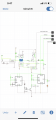
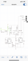
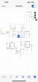
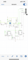
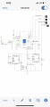
How do you plan to actuate the door? If a switch, the switch shown is a standard switch that charges the cap when the 555 is off. If you use a low-leakage capacitor (like a ceramic cap), it takes no power, Small modification to a DPDT switch will prevent all drain on a battery (after the tiny current to charge the cap) and no other losses through the transistor base.

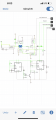
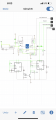
Or do you need a hands-free way to turn this on from a simple spst switch?

E776191A-0279-484A-B909-434B30CC7CB7.jpeg
 

MrSalts

Joined Apr 2, 2020
2,767
This works. Make sure to use a regular diode on the left 555's output as shown.

The amount of time the first one is on can determine how long the second one stays at the lowest frequency. Current values are set for about 1 second. The 1.25Hz signal from the right 555 will start right after power is applied.

CB0ACA7A-F65F-4D5D-8450-141DB55DC679.jpeg
 

Thread Starter

MorganJohan

Joined Mar 3, 2022
17
This works. Make sure to use a regular diode on the left 555's output as shown.

The amount of time the first one is on can determine how long the second one stays at the lowest frequency. Current values are set for about 1 second. The 1.25Hz signal from the right 555 will start right after power is applied.

View attachment 262045
Are you an electrical engineer?
Just wondering how you are quick to figure this out. It’s so cool. I’d like to get to that stage
This all works perfectly. The door is triggered but a DB momentary push button with paralleled holding contacts. Dpst limit switches kill the timing circuits.
 

Thread Starter

MorganJohan

Joined Mar 3, 2022
17
This works. Make sure to use a regular diode on the left 555's output as shown.

The amount of time the first one is on can determine how long the second one stays at the lowest frequency. Current values are set for about 1 second. The 1.25Hz signal from the right 555 will start right after power is applied.

View attachment 262045
Circuit
 

Attachments

Thread Starter

MorganJohan

Joined Mar 3, 2022
17
The switch it pressed. Turns on relays and timing. Door moves changing limit switch state. Touches second limit switch and kills circuit. Press the same button and it goes in reverse turning on timing circuit and motor. Once back to the closed position the limit turns off the circuit again
 

Attachments

MrSalts

Joined Apr 2, 2020
2,767
I didn't go though the latch logic with the switches. The left 555 was getting triggered by the fact that a one-shot triggers on power-up. I'm guessing it is not triggering for some reason. Try adding a 100nF to 1uF cap as shown below.

Also, increase the bandwidth setting of your simulator to 10kHz (under general settings (gear symbol)) to make sure short pulses are caught by the simulator. I think default is 256Hz.

D3019CE0-4B4E-4731-B8A3-39FE8B36845E.jpeg
 

Thread Starter

MorganJohan

Joined Mar 3, 2022
17
I didn't go though the latch logic with the switches. The left 555 was getting triggered by the fact that a one-shot triggers on power-up. I'm guessing it is not triggering for some reason. Try adding a 100nF to 1uF cap as shown below.

Also, increase the bandwidth setting of your simulator to 10kHz (under general settings (gear symbol)) to make sure short pulses are caught by the simulator. I think default is 256Hz.

View attachment 262070
Everything seems to work just fine and I switched it to 10 killerherts it still works
 
Top