555 Sawtooth Generator Circuit analysis

Thread Starter

davidcoll

Joined Apr 30, 2018
16
Hello,
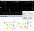
I came across with a 555 periodic sawthooth generator made by crutschow, and i hope that someone can help me understand the "one shot" circuit.
what is the role of the 2 pnp transistors?
and how exactly the sawtooth wave created? is the capacitor charging differently?
I also noticed that if I connect the trigger to the THRS and DIS point, a continuous sawthooth wave is created, why?
I took 3 courses of electronics in the university and its still hard for me to analyze circuits like that.
Thanks for helping.
 

Attachments

dl324

Joined Mar 30, 2015
16,845
Welcome to AAC!

To tag someone, put an '@' in front of their member name.

Q1 and Q2 form a current source that's being used to charge C3. Charging a capacitor from a current source gives a voltage that increases linearly.

When the voltage on the capacitor gets to 2/3 Vcc (8V), the second timer (U2) will discharge the capacitor.

Since both timers have threshold and discharge pins, it would be helpful if you told us which timer you're referring to.
 

crutschow

Joined Mar 14, 2008
34,283
I also noticed that if I connect the trigger to the THRS and DIS point, a continuous sawthooth wave is created, why?
Because when the TRIG input drops to below about 1/3 of Vcc, it triggers the 555 to do another cycle.
So when the signal at the THRS and DIS points goes low at the end to the sawtooth cycle, it triggers the 555 to cycle again, thus creating an astable multivibrator.

I also have a version of the circuit that uses the two transistors in a current-mirror configuration to generate the constant-current.
It has the advantage of the sawtooth period being much less sensitive to changes in the power supply voltage and temperature.
 
Last edited:

Thread Starter

davidcoll

Joined Apr 30, 2018
16
Sorry for the delay, thank you all for the answers! I understand better now.
Because when the TRIG input drops to below about 1/3 of Vcc, it triggers the 555 to do another cycle.
So when the signal at the THRS and DIS points goes low at the end to the sawtooth cycle, it triggers the 555 to cycle again, thus creating an astable multivibrator.

I also have a version of the circuit that uses the two transistors in a current-mirror configuration to generate the constant-current.
It has the advantage of the sawtooth period being much less sensitive to changes in the power supply voltage and temperature.
Amazing! Thanks for the ciruicts and the explanation!
 
Top