555 power consumption

Thread Starter

richbrune

Joined Oct 28, 2005
126

When pulses stop coming in the input, the power consumption of the circuit jumps from 10 mA to 80 mA, is there anyway to lower the power consumption? It's going to kill batteries!
Thanks again, Rich
 

hgmjr

Joined Jan 28, 2005
9,027
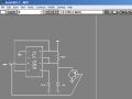
It would help to have a schematic of your circuit so that we may see the details. There may be something that can be done to influence the state the 555 enters when it is not being triggered.

hgmjr
 

Gadget

Joined Jan 10, 2006
614
Your gonna have to upload it somewhere, then direct the URL to it.
Just as a side issue, are you using the CMOS version of the 555 timer..?
 

Distort10n

Joined Dec 25, 2006
429
You select "manage attachments" below the posting field. I have a pretty big monitor so you have to scroll down below "Submit Reply" and you should see it. :cool:
 

hgmjr

Joined Jan 28, 2005
9,027
Are you really trying to drive the 7555's output at pin 3 or is that a drawing oops?

Pin 2 of the device is the /trigger (lo-true) input.

hgmjr
 

Thread Starter

richbrune

Joined Oct 28, 2005
126
That's A Drawing Oops, The Trigger Is At Pin 2, The Circuit Is Working, But It Consumes Alot Of Power When The Timing Cycle Completes.
 

hgmjr

Joined Jan 28, 2005
9,027
I can't see anything in the drawing that you provided that would draw 80 milliamps.

Is there any additional circuitry in the design that is being powered by the battery?

80 milliamps drawn from a 12 volt power source would correspond to 150 ohms.

hgmjr
 

Thread Starter

richbrune

Joined Oct 28, 2005
126
Yes there are, it's a missing pulse detector with a tlo82 amp that provides a zero to 12v inverted pulse to the shown circuit. The first stage of the tlo82 amp operates at a very high gain,and the second stage of tlo82 operates as an inverting buffer ( open loop gain). The second output of the tlo82 goes directly to pin two of the shown 7555 circuit.
 

hgmjr

Joined Jan 28, 2005
9,027
As recommended, temporarily disconnect the circuitry that supports the 555 timer and see what the current measurement is at that point.

This is the old divide and conquer strategy.

hgmjr
 

Thread Starter

richbrune

Joined Oct 28, 2005
126
I disconneted the 7555 circuit shown, and placed a 1 ohm resistor between it's ground and the power source ground--- scope reads 80mv. Could the PNP transistor base allow that much current? This is an soic/1206 circuit, so placing probes and jumpers is very difficult.
 

hgmjr

Joined Jan 28, 2005
9,027
Try measuring the voltage across the 1 ohm resistor using a voltmeter as a cross-check.

The PNP common collector stage with the 510K ohm emitter resistor should not draw that much current at all.

hgmjr
 

hgmjr

Joined Jan 28, 2005
9,027
What do you have connected to the output pin (pin 3) of the 7555 other than the base of the PNP transistor?

hgmjr
 

Thread Starter

richbrune

Joined Oct 28, 2005
126
I managed to get a 1 ohm resistor in line with the base of the PNP, and it's also giving me 78mV. Anyone know a substitute MOS for that PNP?
 

hgmjr

Joined Jan 28, 2005
9,027
Are we talking about an actual circuit or are we talking about a simulation of a circuit?

If it is an actual circuit then try putting a 1K ohm resistor in series with the 7555's output pin (pin 3) and the base of the transistor. This should not adversely affect the circuit since the input impedance of the PNP base should be very high. Then measure the current draw and see what you get.

hgmjr
 

hgmjr

Joined Jan 28, 2005
9,027
Are you very sure that the transistor is not connected up incorrectly?

The base current of a common collector transistor stage should be very low. Definitely less than a milliamp.

hgmjr
 
Top