555 Debounce on the + Side?

Thread Starter

Dan-O

Joined Jul 26, 2009
38
Hello folks, first time posting so go easy on me.
I'm an amateur that knows just enough to get into trouble.

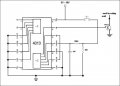
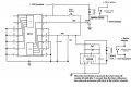
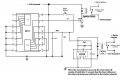
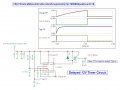
I'm designing a vehicle pushbutton start using a 4013 flip flop circuit for the vehicle power and a 555 with a 1 second delay for the start function.

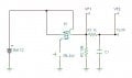
In planning ahead, I think I might need a debounce for the input to the 4013 so I don't flop when I want to flip.
(Sorry about the bad joke)
The input to the 4013 is a +12V input controlled by a relay activated by a momentary switch.

Could someone point me to a debounce that's on the + side of the input instead of the usual - side that I find?
Thanks for the help.
Dan
 

Thread Starter

Dan-O

Joined Jul 26, 2009
38
Have you considered just using simple a RC input to the FF?
Do you have an idea on what values I should use for the components?
Most of the RC circuits I find are negative trigger. Is it a matter of reversing the cap in the circuit?
Please forgive my ignorance of stupid questions.
 
Last edited:

CDRIVE

Joined Jul 1, 2008
2,219
Do you have an idea on what values I should use for the components?
Most of the RC circuits I find are negative trigger. Is it a matter of reversing the cap in the circuit?
Please forgive my ignorance of stupid questions.
I would think a 1K resistor on the switched side of the push button and a 0.01uF to 0.1uF to gnd should do.
 

CDRIVE

Joined Jul 1, 2008
2,219
Thank you I appreciate the help.
I just re-read your first post and I made a boo boo! If the FF is being triggered by the contacts of a relay then the RC filter should be connected to the switched side of the relay contacts, not the switch . Sorry....! :eek:
 

Thread Starter

Dan-O

Joined Jul 26, 2009
38
Please see attachment. Is this how you're wired?
Yes. I knew you meant to connect the RC components on the relay side.
I am using the 4013 circuit here--> Click Link but with a relay instead of the switch.
So if I'm reading it and your suggestions correctly, it already has the 'debounce' built in?
Thanks again for the help.
 
Last edited:

CDRIVE

Joined Jul 1, 2008
2,219
Yes. I knew you meant to connect the RC components on the relay side.
I am using the 4013 circuit here--> Click Link but with a relay instead of the switch.
So if I'm reading it and your suggestions correctly, it already has the 'debounce' built in?
Thanks again for the help.
Yeah, that circuit already has a 100K and a 1uF cap in there. That should give ample immunity from contact bounce. ;)
 

Thread Starter

Dan-O

Joined Jul 26, 2009
38
Well, I finally had a few minutes to tinker.
I'm having some issues.:(
The 4013 is really sensitive to noise/contact bouncing.
I think I might need a more aggressive way to debounce the + switch input to the 4013.
I misspoke in an earlier post, I do have a switch input not a relay input to the 4013.
I am using the 4013 circuit here--> Click Link

The way my circuit works is by holding a shared pushbutton + input (both the 555 and 4013 share the same + input)
A relay engages and the engine cranks through the 555 after 1 second. That end works perfectly. But, as soon as I release the switch, the 4013 shuts off the vehicle power relay.
Suggestions?

Also, should I have a diode or a resistor from 11 to my transistor? I'm using a 3904 with the base connected to pin 11 of the 4013.

Thanks for the input.
Dan
 

CDRIVE

Joined Jul 1, 2008
2,219
Dan, could you please post your complete schematic? It will make diagnosis much easier. As they say "A picture is worth a thous..... "
 

Thread Starter

Dan-O

Joined Jul 26, 2009
38
I found a schematic of what I'm doing with the 3014 and modified it with the transistor I have to control the relay coil. Not pictured is the usual clamping diode across the coil for spikes.
I appreciate the help.
Dan
 

Attachments

Last edited:

Thread Starter

Dan-O

Joined Jul 26, 2009
38
Thanks, I added it.
Do you think that was angering the 3014 and causing my issue?
I added the 555 and updated my schematic.
 

Attachments

Last edited:

CDRIVE

Joined Jul 1, 2008
2,219
You have a few things wrong here.
(1) The base resistor should be ~ 1.0K not 100K. 100K will not provide enough base current.
(2) The 555's vcc (pin8) should be connected to the 12V supply.
(3) You may also need a driver transistor for the 555 relay coil. What's the current draw for that relay.

There may be more but I have to get some sleep.
 

Thread Starter

Dan-O

Joined Jul 26, 2009
38
Current draw is low, it's not a typical Bosch relay. I have to look it up, but I believe the coil resistance is up there, like 720 ohms or so.
I made some revisions to my schematic.
Thanks for the help.
Dan
 

Attachments

Thread Starter

Dan-O

Joined Jul 26, 2009
38
Hmm, there's a few things I don't understand: What are the TP notations in the schematic?

Actually, I don't have an issue with the 555 doing it's job; the 1 second starter delay is working great.
The issue I have is with the 4013 not changing state.
 
Top