4017 CMOS interference

Thread Starter

magnet18

Joined Dec 22, 2010
1,227
No, i believe its that pin 15 goes high when either the reset line goes high OR when the output pin 5, to display the numeral 6, goes high.
and correct me if im wrong, but for that AND circuit its when the pin on the right of the resistor both pins on the left side would go high... the resistors are to protect the diodes? (when functioning independently)
 
Last edited:

Wendy

Joined Mar 24, 2008
23,800
Nope, I've used this chip now and again, pin 15 is the reset input, pin 5 is number 6 in the sequence, an output.


I pointed to the article, you really need to read chapters 1 and 2. All LEDs need a resistor, this is fundamental. I also have quite a few circuits for the 4017 (the 4022 is a kissing cousin, it has 8 outputs instead of 10) in the article.

LEDs, 555s, Flashers, and Light Chasers
 

Thread Starter

magnet18

Joined Dec 22, 2010
1,227
Bill, as far as i can tell were saying the same thing, when the output pin #5 goes high, it trips the chip reset, pin #15. pin 15 can also be tripped by the master reset.

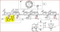
Ive attached a edited version of the overall schematic,
overall-edited.JPG
the yellow are being the area i believe im having trouble with, the red circled areas being the areas you said were unnecessary, the blue lines being where i intend to run a line with a switch to the 8Hz out pin on the 4060 to set the clock.
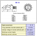
The dtasheet for the tubes im using can be found here if your interested.
 
Last edited:

Audioguru

Joined Dec 20, 2007
11,248
I started in electronics about 50 years ago and I have never seen an old Nixie tube.
In those years I used and saw a lot of test equipment but none used old nixie tubes.
Why do you use them?
 

hgmjr

Joined Jan 28, 2005
9,027
Bill, as far as i can tell were saying the same thing, when the output pin #5 goes high, it trips the chip reset, pin #15. pin 15 can also be tripped by the master reset.

Ive attached a edited version of the overall schematic,
View attachment 25772
the yellow are being the area i believe im having trouble with, the red circled areas being the areas you said were unnecessary, the blue lines being where i intend to run a line with a switch to the 8Hz out pin on the 4060 to set the clock.
The dtasheet for the tubes im using can be found here if your interested.
I like the nostalgia of nixies. I hope you will be sure to provide a photo of the finished product.

hgmjr
 

Thread Starter

magnet18

Joined Dec 22, 2010
1,227
Yea, i noticed the lead in wire was glowing and it shouldn't, the tubes were also getting hot after a couple of minuets, i assumed that this wasn't normal as they are supposed to be "cold cathode". I believe its because the transformer im using is 180V and the tubes are 170Vmax rating. I was actually planning on installing a potentiometer in the line into the transformer, to both fix the problem and for a dimmer, and then have a switch in the line to shut the tubes off altogether while keeping the logic running.
Would this work well?
 
Last edited:

hgmjr

Joined Jan 28, 2005
9,027
@ audioguru, like they said, i love the look, i personally love the look of the IN-14's :D
@hgmjr, i paln to post a pic, but dont hold your breath, it may be quite awhile, heres a linlk to what it currently looks like if your curious http://www.youtube.com/watch?v=4dmVFIjPuXQ
@bertus, thanks for the links :)
Thanks for the link to the Youtube of your setup. I have to agree with Bertus, the digits appear to be overdriven and therefore difficult to read. If you could place a colored piece of plastic filter material in front of the Nixies it would be easier to discern the numbers.

hgmjr
 

Thread Starter

magnet18

Joined Dec 22, 2010
1,227
The digits themselves actually appear normal (maybe a bit too bright) when viewed in real life, the hazyness of the numerals is mainly due to the fact that the video was taken with my phone, which is not very good at all at adjusting contrast.
I do however agree that they are nonetheless overdriven.
 
Last edited:

Wendy

Joined Mar 24, 2008
23,800
I started in electronics about 50 years ago and I have never seen an old Nixie tube.
In those years I used and saw a lot of test equipment but none used old nixie tubes.
Why do you use them?
This is interesting, since I've used many older pieces of equipment that had nixies. They worked really well, and included both digital voltmeters and frequency counters. Some of this equipment was used to build space age equipment, including the space shuttle. This is back when I worked for Rockwell International, and during my stint as a metrology tech. Just because a piece of equipment is old is no reason to scrap it. I've only been doing this for 30 or so years.
 

JoeJester

Joined Apr 26, 2005
4,390
Audioguru,

I started 40 years ago and used nixie tube frequency counters. I've used dividers that were beam switching tubes. Granted the equipment was from a late 50s/early 60s design. I've also worked on equipment that used phantastron oscillators. That was from a late 40s/early 50s design.

By the end of the 70s the nixie tube test equipment was replaced, although there were some places that still had them in the closet. Once they hit the "ham" circuit, they stay around for a bit.
 

Thread Starter

magnet18

Joined Dec 22, 2010
1,227
To draw attention back to my question,

The transformer im using is 180V and the tubes are 170Vmax rating. I was actually planning on installing a potentiometer in the line into the transformer, to both fix the problem and for a dimmer, and then have a switch in the line to shut the tubes off altogether while keeping the logic running.
Would this work well?
 

marshallf3

Joined Jul 26, 2010
2,358
You'll burn the tubes out if you don't limit the input voltage to a reasonable level AND make darn sure you aren't exceeding the normal current it takes to drive a digit.

I've got some of this stuff buried out in my garage as well, very old HP rack mount test equipment, but it hasn't been powered up in such a long time that I'll have to be very careful bringing it back up so the electrolytics don't explode on me.
 

bertus

Joined Apr 5, 2008
22,974
Hello,

I looked up the data of the nixie and it says that the current is 2.5 mA.


Not limiting the current will lead to dead spots, so the numbers will not be completely illuminated.

Bertus
 

Attachments

SgtWookie

Joined Jul 17, 2007
22,230
Magnet18,
I'd encourage you to poke around on Ronald Dekkers' fine site:
http://dos4ever.com/

He has a number of Nixie-tube related projects. You'll find his site very fun and very informative.

I suggest starting with the "Flyback Converters for Dummies" page.
 
Top