40 Second 555 time on ( one Shot )

Thread Starter

Werner Slabbert

Joined Sep 6, 2017
6
Hello Everyone

First off i am a complete NOOB at circuitry and the like, what i know is basically what i can sumize from a picture.

so here follows my question, i need to have a sort of variable timer that can run a small 3v to 12v motor WITH a red LED for 1 to 60 seconds using a pot switch, and when the " time " is done revert to a dormant state until the micro switch is triggered again. I have heard that this might be accomplished using a NE555P chip.
PS: if you reply please supply pictures.
I Have the LED circuit working or rather switching colour as needed , but it only works while the micro sw is activated, i need the whole circuit to be in the "Working" state for the set time and then "Wait" for trigger
Regards
The Pixie Joe
 

wayneh

Joined Sep 9, 2010
18,100
How precise does your timing need to be? A 555 can do a fine job as long as ±5% or so is acceptable.

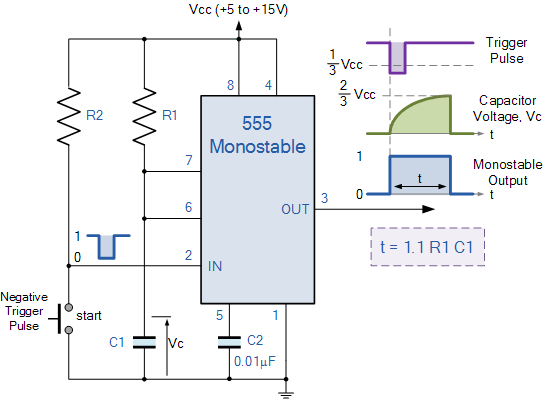
A full minute is a "long time" for a 555 but doable. As you've already learned, you need a one-shot, or "monostable multivibrator".

Here's one (R1 would be replaced by a resistor and a pot):
 

crutschow

Joined Mar 14, 2008
38,478
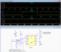
Here's the LTspice simulation of the 555 circuit with part's values:
Pot U2 gives a one-shot range of about 0.8s to 74s.
(Note that the microswitch on time must be less than the one-shot period).

upload_2017-9-7_8-56-21.png
 

AnalogKid

Joined Aug 1, 2013
12,114
I have heard that this might be accumplished using a NE555P chip.
For a period this long, I recommend a CMOS 555 version, like the LMC555. This will allow you to use a larger timing resistor and smaller timing capacitor, a good thing. In Wally's circuit, this could be a 47K fixed resistor (R2), 500K pot (U2), and a 100 uF capacitor (C1).

ak
 

Ylli

Joined Nov 13, 2015
1,092
In addition, looking at Crutschow's circuit.... Leakage in large value tantalum/electrolytic capacitors (C1 in this case) can sometime produce unpredictable results. Fix is to connect the capacitors (-) terminal to pins 6 & 7 and the (+) terminal to V+.
 

crutschow

Joined Mar 14, 2008
38,478
Fix is to connect the capacitors (-) terminal to pins 6 & 7 and the (+) terminal to V+.
That connection starts the period with the full supply voltage across the cap which is reduced to about 1/3rd the supply voltage at the end of the period.

The standard connection starts the cap voltage at zero with a maximum of about 2/3rd of the supply voltage at the end of the period.

Your connection would generate more maximum leakage, but the leakage is in parallel with the timing resistor so would tend to shorten the period, while the leakage in the standard connection would lengthen the period.
For high leakages your circuit would work even if the leakage is greater than the charge current through the timing resistor, whereas the standard connection wouldn't.
 

Thread Starter

Werner Slabbert

Joined Sep 6, 2017
6
How precise does your timing need to be? A 555 can do a fine job as long as ±5% or so is acceptable.

A full minute is a "long time" for a 555 but doable. As you've already learned, you need a one-shot, or "monostable multivibrator".

Here's one (R1 would be replaced by a resistor and a pot):
Thank you for the prompt reply, my predicament here is i have literally no electrical background, so basically what i understand here is that i need to change R1 for a Pot & resistor, but what size resistor? and how would i connect it? and then i see that Pin 8 & 3 are "Out" so would i then connect the motor and Red LED to these points?
I Apologise for my lack of knowledge in this regard, i know it's very frustrating to try and explain to a laymen like me. your patients is greatly appreciated.
Thank you again
wayneh
 

Thread Starter

Werner Slabbert

Joined Sep 6, 2017
6
Thank you all for the replies... i will have to google a lot of the information here it might take me some time to figure it all out, but thank you none the less.

the project i am trying to build is easiest to explain like an ATM Bank , when you insert the card into the slot the micro sw is activated and the motor on the "Feeder" swallows the card ( in my project though the card does not need to be returned.) and once the micro sw is activated the LED has to change from green to red and stay red for the set time ( hence the Pot sw ) but the motor itself ( that retracts the card only has to be active for about 6 to 10 seconds of the total "set" time as i mentioned above.
I hope this will clarify my problem a little.
 
Your in a weird time space. Most would use a processor like www.picaxe.com as an example.

Timerblox works for 33 seconds easily. http://www.linear.com/product/LTC6993-1

Even this https://www.google.com/search?client=ubuntu&channel=fs&q=programmable+555+timer&ie=utf-8&oe=utf-8 might work.

e.g. Two timers. One for the motor (whole time) and one for the LED (Led time). They are both triggered don card insertion.

This http://www.customsiliconsolutions.com/downloads/Revised Standard products/CSS555C_Spec.pdf timer is likely available at www,Jameco.com. Much longer delays are possible, like weeks. It does have to be "programmed"

Depends on how much effort you want to put into it.

Power supply and micropower may enter into your design which can complicate things.
 

Thread Starter

Werner Slabbert

Joined Sep 6, 2017
6
Your in a weird time space. Most would use a processor like www.picaxe.com as an example.

Timerblox works for 33 seconds easily. http://www.linear.com/product/LTC6993-1

Even this https://www.google.com/search?client=ubuntu&channel=fs&q=programmable+555+timer&ie=utf-8&oe=utf-8 might work.

e.g. Two timers. One for the motor (whole time) and one for the LED (Led time). They are both triggered don card insertion.

This http://www.customsiliconsolutions.com/downloads/Revised Standard products/CSS555C_Spec.pdf timer is likely available at
www,Jameco.com. Much longer delays are possible, like weeks. It does have to be "programmed"

Depends on how much effort you want to put into it.

Power supply and micropower may enter into your design which can complicate things.
Hi K.I.S.S.
Thanx for the reply, like your Tag suggests i need it as simple as humanly possible. so programming is a total no go.
Regards
 
The programmable 555 timer just means running a program to set parameters to get the longer times.

So, i also suggested getting something that's already put together. We don;t know your other constraints. e.g.
Power supply you want to use - battery or wall
Your general location in the world? - Just country would suffice
- Helps us to find ready made stuff
Is power consumption when not doing anything important?
 

Thread Starter

Werner Slabbert

Joined Sep 6, 2017
6
Hi K.I.S.S

i am based in south africa
my power supply will be a 24 vdc i have found an adjustable dc/dc Buck module to adjust incoming voltage down to 1.5v if needed.
No the power consumption is not relevant as the machine it piggy backs on will be on 24/7
I hope this helps
 
It probably makes the 555 approach more viable for you. When you start adding large capacitors, their imperfections will affect the timing, accuracy and repeatability. I'd check ebay for timing modules you might be able to use.
 

Reloadron

Joined Jan 15, 2015
7,882
What you are looking for is a "One Shot" timer or timer relay. Sometimes it becomes easier to buy a canned solution rather than build a circuit. There are likely a dozen or more manufacturers that have what you want, the trick being to find a distributor in your area, South Africa. This is a pretty good overview of Understanding Time Delay Relay Functions presented by Macromatic one such manufacturer. For example:

SINGLE SHOT, One Shot, Momentary Interval
Upon application of input voltage, the time delay relay is ready to accept a trigger. When the trigger is applied, the output is energized and the time delay (t) begins. During the time delay (t), the trigger is ignored. At the end of the time delay (t), the output is de-energized and the time delay relay is ready to accept another trigger.

Units like this are made to work off a variety of voltages such as 12 and 24 VDC among other supply voltages. Most offer a wide range of timing and many are easily mounted in a simple 8 or 11 pin socket making for an easy installation. I suggest a simple Google of "one shot timer relay" as a start so we can see what is available through what distributors in your specific area.

Ron
 
Top