Facebook
 Google
 GitHub
 Linkedin
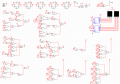
I'm building a basic 30-second countdown timer project using only TTL logic components, no microcontrollers. I’m a student and doing this in Multisim.
A push button adds 5 seconds (up to 30 seconds max).
A 7-segment display shows the remaining time (in seconds).
An LED indicator lights up when time remains (OFF if 0).
Time automatically counts down every second.
Please help me
A push button adds 5 seconds (up to 30 seconds max).
A 7-segment display shows the remaining time (in seconds).
An LED indicator lights up when time remains (OFF if 0).
Time automatically counts down every second.
Please help me