36v 3ph charger conversion to single phase

Thread Starter

frankr2994

Joined Apr 30, 2020
36
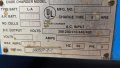
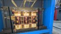
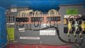
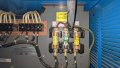
Hi everyone. I manage a small automotive shop and we just purchased a used 36v fork truck. It came with a Exide 3ph charger. We don't have the ability to get 3 phase at the shop and on a budget. For the time being we purchased a golf cart charger that runs on 110v to charge the lift. Battery is 750ah and the charger is 21amp. I only want to use this temporarily. I have read that I can wire all the transformers using both hot legs of a 220v single phase circuit and have all the transformers connected in parallel. I've done home and automotive wiring all my life but this is quickly above me. I don't have an issue wiring it up like stated what I have an issue with is if it will work. I know that I have to switch the jumpers to the correct voltage. The previous owner had it running on 480. I attached a few pictures if it helps. I also have the service manual and wiring schematics for the charger. If this cannot be done then I have an idea on building a 60amp charger but I'll cross that road if needed later. Would love to be able to get this 100 amp charger to push something decent. I understand that it probably won't be able to output what it would on 3ph. Any and all help is appreciated.
Thanks,
Rob
 

Attachments

Thread Starter

frankr2994

Joined Apr 30, 2020
36
Anyone? I would have guessed someone would have at least told me this was dumb by now. We got our golf cart charger today. What I've found out is the onboard soc indicator is wrong on the fork lift by a bit. That little charger brought the battery to near full in about 4 hours. I'm going to wire up an onboard volt meter and just tape a little volt reference chart to monitor the soc.
 

Thread Starter

frankr2994

Joined Apr 30, 2020
36
May I ask why? I'm including images of diagrams listed from the factory manual on the connections. each line currently has 2 wires coming off and is equally split up to the transformers right now. As in L1 has leads 1 and 2 coming from it. 1 goes to TB3 and 2 goes to TB2. L2 has leads 3 and 4, 3 to TB1 and 4 to TB2 and L3 has 5 and 6, 5 going to TB2 and 6 going to TB3. Obviously all lines are split so there should be equal current draw from the 3ph line in. I'm obviously a novice in electrical but running a cap off of L2 would still just pull way more current on 1 line.
240v wiring.PNG
ac input.PNG

So I guess my question is from 3 phase to single whats the difference when each transformer is only getting 2 hot legs either way? here is a crude drawing of what I would be talking about doing.

single phase sample.png
 

Danko

Joined Nov 22, 2017
1,834
May I ask why?
Here is the same wide used principle, as in 3-phase motor running from 1-phase source with help of capacitor.

See, for example, https://www.garagejournal.com/forum/threads/converting-a-3-phase-welder-to-single-phase.115887/

So I guess my question is from 3 phase to single whats the difference when each transformer is only getting 2 hot legs either way? here is a crude drawing of what I would be talking about doing.
With use only two L1 and L2 lines, out current will dramatically lower and will have big pulsations.
 
Last edited:

Thread Starter

frankr2994

Joined Apr 30, 2020
36
Ok. I've read through that on converting the welder. I understand that welder and this charger are very similar. My question for you is in the example you had me read through they are using 2 caps. L1 and L2 both have caps going to the same transformer vs your suggestion of using 1 cap. Would you care to continue to school me?
 

Danko

Joined Nov 22, 2017
1,834
Ok. I've read through that on converting the welder. I understand that welder and this charger are very similar. My question for you is in the example you had me read through they are using 2 caps. L1 and L2 both have caps going to the same transformer vs your suggestion of using 1 cap. Would you care to continue to school me?
1. Capacitors and two half-windings of phase B - all are connected in series, does not matter, what is order of them.
2. Capacitance of two capacitors 60μF in series equal 60/2=30μF only. Seems author measured phase shift in iddle state, so 30μF was enough, but not for full load.
3. Winding leads of phase C are swapped. It is not nesessary, when used circuit in post #3.

So, you can buy 4 capacitors 80μF (see left picture below), $11.20 each, and connect them in parallel. Number of parallel connected capacitors is defined by minimum pulsation of out current at 100A.
If 1 or 2 capacitors will not used, they simply will spare parts (important!).

Windings of your charger should be configured for 3-phase 240VAC !
1635872124680.png1635856985567.png
 
Last edited:

Thread Starter

frankr2994

Joined Apr 30, 2020
36
Please review this again crude drawing. If going with Post 3 where you state I can use a 300uf cap is how I would need it wired? single phase sample 2.png
Your help is greatly appreciated.
 

Thread Starter

frankr2994

Joined Apr 30, 2020
36
Thank you very nice for the schematic and detailed information on why its done this way. Greatly appreciated. I can't believe it can be done so simple. I'm going to track down a couple good quality 300uf caps so I can have a spare. Thanks again
 

Danko

Joined Nov 22, 2017
1,834
Found a cap that looks large enough to handle this. digikey 300uf cap . unless told other wise I'll order 2 of these.
900V - good voltage.
300μF - approximately calculated by maximum power,
but exact value of capacitance you can define by experiment only,
because of unknown electromagnetic parameters of transformer.
Therefore, buy capacitors with lower capacitance.
And in parallel every capacitor will see lower current - it is good for its life.
 

Thread Starter

frankr2994

Joined Apr 30, 2020
36
What exactly should I be looking at when testing to see if the current capacitors are working correctly? from your other post on buying 4 80uf caps and possibly using 3 of them. How do I know to go from 2 to 3 or 3 to 2 in parallel?
 

Danko

Joined Nov 22, 2017
1,834
I downloaded manual for charger D3E-18-680B.
It not contains rectifier and filter as welder does, but 36V from secondary goes direct to SCRs (thyristors).
This method - shift phase using capacitor will not work with such charger circuit configuration.
No phase shift, only giant extra currents through capacitor - SCRs. Charger will damaged in seconds.
Sorry, no way... Will think about your problem.
-----------------------
Look at this device. You can not only run 3-phase motors with it, but your charger too...
https://aliexpress.ru/item/4000171349173.html?sku_id=10000002420810256
1635885070572.png1635885159938.png
 
Last edited:

Thread Starter

frankr2994

Joined Apr 30, 2020
36
Well many thanks anyways. Very much appreciated. If you do come up with a solution for me in the future I'd appreciate that very much as well. As far as you going the extra step to go through the entire wiring schematic you just saved me from destroying the charger which if I flat out just can't use I'll end up selling it.

Thanks again,
Rob
 

Thread Starter

frankr2994

Joined Apr 30, 2020
36
Ok I guess I missed what you posted there about the inverter. Looks interesting. I Know its from aliexpress but being 4kw that seems really cheap compared to an actual phase convertor. I would imagine with a device like that there would be some initial setup to get it programmed to what I need since I don't actually want to vary the speed of anything. Very good find!
 

Thread Starter

frankr2994

Joined Apr 30, 2020
36
Here check this one out. I could not find that exact one on aliexpress.com which is what I would use but I found what looks to be the same device. Page seems to have alot more info though. 3 phase inverter . Let me know what you think.
 

Danko

Joined Nov 22, 2017
1,834
VFD inverter can be used only with motor. It may supply 3-phase transformer if motor connected to its secondary.
https://www.wolfautomation.com/blog/when-not-to-use-a-vfd/

Best (not cheap) way to obtain real 3-phase power (about 7HP)- is using this converter:
https://www.northamericaphaseconver...-converters/pro-line-rotary-phase-converters/

Maybe acquisition of modern charger can solve problem:
https://www.alrightpower.com/battery-charger/3600w-36v-100a-battery-charger/
https://www.alibaba.com/product-det...6.html?spm=a2700.wholesale.0.0.40a95477X78d1Y
 

Thread Starter

frankr2994

Joined Apr 30, 2020
36
I do have questions about the vfd though. In my reading I've found that a few people have asked about using them for 3 phase welders. The issue with a welder is the current hits every time an arc is struck. A typical welder draws very little until your actually welding. I can see this being a huge problem for something like a vfd to try and control. However in something like a charger the current is usually ramped up to max output. I've never seen one just hit with full current. Then that current will stay there and taper off gradually. I know there is an actual charge algorithm designed into this charger but any of the modes should not be sharp hits. It will just change how heavy the constant charge is. So given that I could even go larger for not much more on a vfd say a 7.5kw model and set it to 60hz and leave it. Is there a reason that modified 3 phase won't work? The closest thing I've found online about this doesn't really fit. I found a few people ask about trying to control a 3 phase electric heater. The reason the idea was shot down is you cannot control the output of a resistive load by changing the frequency. The individuals actually wanted to change how much heat the heater was making. I don't want to change any output of the charger. It seems that this specific question was not answered or asked anywhere on the net I can find.
 
Top