Facebook
 Google
 GitHub
 Linkedin
Hi,
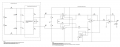
I have created a 3 chip instrumentation amplifier using an LM324 Op-Amp for a project. I have simulated the circuit in Circuit Lab using a differential DC input voltage of 3.5mV. The gain is approx. 982 and I have split this up providing roughly 18 in the amplifier and 54 in the first stage.
The circuit works as expected in simulation, however I have built this on the breadboard and the only way I can get it to work is by connecting the virtual ground of the 9.1V Zener split rail supply to the common or zero volts on a separate split rail bench power supply.
This poses an issue, as the idea of the Zener split rail supply was to provide stable voltages from two 9 Volt batteries connected in series, so the transducer could be placed elsewhere and powered from a separate supply.
The only connection between the simulated transducer circuit and the instrumentation amplifier was to be the two sense wires from the transducer to the IA.
I have provided a link to my Circuit Lab model for further information, and attached a picture of the circuit.
I am hoping to get some information as to what I could try, or perhaps some direction and guidance in relation to what is not immediately obvious to some my problem.
https://www.circuitlab.com/circuit/7jn33336vqnk/ia_with-zenner_circuit/
Also, there is a slight difference between the finished build and the simulated, which is the inclusion of an output offset adjustment circuit, which uses a non-inverting buffer and 10Kohm potentiometer. The output of the buffer is connected to the other side of R13, so I have removed the ground reference. However, I don't believe this contributes to the issue I have described.
Regards,
Dan
Attachments
-
 71.3 KB Views: 29