hi ckt,
Is this the Model you have tried.?
What errors did you find.?
E
.MODEL J2N5457 NJF(Beta=1.125m Betatce=-500m Rd=1 Rs=1 Lambda=2.3m Vto=-1.372 Vtotc=-2.5m Is=181.3f Isr=1.747p N=1 Nr=2 Xti=3 Alpha=2.543u Vk=152.2 Cgd=4p M=311.4m Pb=500m Fc=500m Cgs=4.627p Kf=1.045e-002f Af=1)
@ericgibbs, this is the same model as provided by @Bordodynov. The drain curve in proteus for this model is shown below.
This model shows that, for Vgs=0V the Idd is 400uA and Vp=1.9V but the minimum value of Idds is 1mA(datasheet: https://global.oup.com/us/companion...icrocircuits/students/mos/2n5457-motorola.pdf).
while I understand that the spice model may not always be accurate and that there is wide spread of electrical characteristics in the same transistors due to manufacturing process, I still think that the model is not within acceptable level. but this is my view, the model could be correct so I was looking for more spice model to experiment.
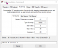
hmm if the spice model is good then it looks like there is something wrong with my drain plot in proteus but cannot find the reason. I have set the following in properties for dc transfer characteristics curve.
and the probes on the circuit for drawing drain curve is,
hmm if the spice model is good then it looks like there is something wrong with my drain plot in proteus but cannot find the reason. I have set the following in properties for dc transfer characteristics curve.
hi ckt,
I have one query ref your image, are you sure of the vertical scaling, it uses 'm' which indicates milliamps .
If that is correct, the first plot shows 0 to 11mA scaling,? Post #11
So the plots are around 0.5mA
which matches with @eetech00 graph in post #10 which shows 1mA at the top(but don't know what is Vgs for this curve).
But @ericgibbs circuit shows positive supply to the gate, I don't know whether it is due to this reason the drain curve is showing 1mA instead of 0.4uA for Vgs=0 and maybe @eetech00 is also using positive gate bias.
Because when I use positive gate bias I also get the similar curve as shown below,
But a JFET(n-channel) on a drain curve has max current Idss when Vgs=0V and negative bias Vgs is only applicable.
So what is going on here? is proteus wrong or model wrong or have i mistake somehere?
But @ericgibbs circuit shows positive supply to the gate, I don't know whether it is due to this reason the drain curve is showing 1mA instead of 0.4uA for Vgs=0 and maybe @eetech00 is also using positive gate bias.
Because when I use positive gate bias I also get the similar curve as shown below,
Are you sure you've mapped the .subckt pins to the symbol correctly in the proteus library? Probably should recheck.
I am using 0v to -1v stepping on gate as is shown on the datasheet. You should be also.
In the graphic below, the top trace in each pane is the waveform at 0v vgs. The bottom trace is the waveform at -1v vgs.
You can see Id is at max (about 1ma) when vgs=0.
 Facebook
 Google
 GitHub
 Linkedin