 Facebook
 Google
 GitHub
 Linkedin
Hello all,
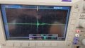
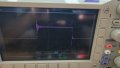
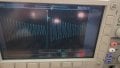
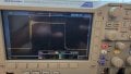
I'm having this issue where my Fly-back power supply is not outputting clean 24VDC.
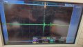
I have attached images of what the scoped waveforms looks like
I have tried adding a 28V zener (SMBJ5362B) and a 2200pF cap (VY1222M47Y5UQ63V0). None of this helped.
I've followed the recommend circuit analog devices has provided and the issue is still there.
Does anyone have any recommendations?
Would a zener at 26V help?
I'm having this issue where my Fly-back power supply is not outputting clean 24VDC.
I have attached images of what the scoped waveforms looks like
- Gate voltage at FET: Scope CH1 Yellow
- FET drain voltage: Scope CH2 Blue
- Gate voltage at pin 19 of LT8316: Scope CH3 Purple
- Output voltage ripple across cap C86: Scope CH4 Green
I have tried adding a 28V zener (SMBJ5362B) and a 2200pF cap (VY1222M47Y5UQ63V0). None of this helped.
I've followed the recommend circuit analog devices has provided and the issue is still there.
Does anyone have any recommendations?
Would a zener at 26V help?
Attachments
-
 407.5 KB Views: 42
 -
 365.8 KB Views: 42
 -
 432.4 KB Views: 37
 -
 423.5 KB Views: 37
 -
 606.1 KB Views: 37
Last edited:


