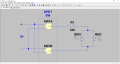
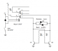
Yes, the LED lets you know whether the relay is switched on or off. It runs a "fat" switch on the plates of the tube. The ground reference needed to be elevated to reduce hum.
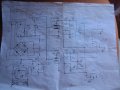
I messed up again! I'm using a DPDT relay. I'll attach the whole schematic. Maybe that will make it easier to understand. It's a musical instrument preamp.
The LED circuit below is what I've decided that I need. The switch idea is fine, but I also have a foot switch option. I wonder what the ideal values for the resistors would be if I were to use this in the circuit. I'm Nbtone, by the way. I couldn't remember my password, and the password reset doesn't work. This way there are no transistors.
There is a constant flow of current when the relay is switched on. When it is switched off the only current flowing is for the LED. I'm not sure how it could be more efficient?
There is a constant flow of current when the relay is switched on. When it is switched off the only current flowing is for the LED. I'm not sure how it could be more efficient?
View attachment 113764
Here is a more complete schematic. The relay shows only one side, and there are two circuits that it switches. I was a little confused about where I was finding the voltage. I went and spent some more time studying, and these are correct voltages. The two 100 ohm resistors used to go straight to ground, but I've had to do some ground referencing. Now the LED won't work. Sorry about the earlier posts.
The two ground symbols only mean that the current flows through the LED to ground from the opposite B+. I haven't built one with this design in this circuit yet. I know that it works, because a built it in a variation on the circuit that I'm going to use. The problem is that I'm getting a much higher reading for the forward voltage. I made a DC filament supply and tried it. The circuit I've shown uses an AC filament supply.
The two ground symbols only mean that the current flows through the LED to ground from the opposite B+. I haven't built one with this design in this circuit yet. I know that it works, because a built it in a variation on the circuit that I'm going to use. The problem is that I'm getting a much higher reading for the forward voltage. I made a DC filament supply and tried it. The circuit I've shown uses an AC filament supply.

 Facebook
 Google
 GitHub
 Linkedin