1975 Circuit and I am trying to decipher it

Thread Starter

ChrisRaven

Joined Nov 9, 2025
6
Hi all: Not sure if there is anyone out there that wants to laugh along with me but I could use the company. I got my hands on a 1975 Cordovox accordion along with 3 tone generator cabinets and 2 - 200 watt amplifier cabinets. After a lot of research I did manage to get my hands on a complete set of schematics, (without these I would be dead in the water...lol). I do have some electronics training from 1972 so yup I'm an old guy, but open to attempting all kinds of things. I have some good meters, and a 4 channel Tek scope so at least I can get some good readings. Here's my situation; I know just from past experience that all the caps should be replaced, some are leaking but after 50 years I think it is probably a good idea just because.
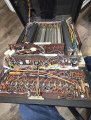
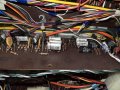
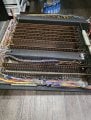
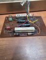
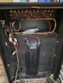
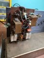
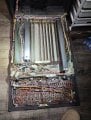
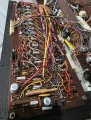
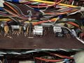
Now my problem is I am not good enough to look at a circuit and say what it is supposed to do, plus the numbers on the parts do not look like real numbers so I am not to sure how to get either replacement or substitute parts. For example there are 2 transistors with GE (That's straight forward General Electric, and the next line says P15000 and under that is 7225. I did some looking for the P15000 and came up with nothing. I can attach the schematic for the power supply which shows some of the voltages. I am 99 percent sure that I do not have all the correct voltages. Where is is saying +and - 35 VDC I am getting + and - 40 VDC Not quite sure how I would get that back to the required 35 volts. Z1 is a 20 volt zener and the output from the emitter of Q113 is actually + 19 volts like it should be. However when looking at Z2 which is a 22 volt zener and the output of Q115 is supposed to be -20 volts I am getting -19 volts. If you have a look at the schematic you can see there is quite a list of different voltages that are required to run these circuits in the accordion and the tone generators. The Tone Generator cabinet is a massive thing, 22" wide, 36" high and 11" deep and completely loaded with circuits. I have 3 of these so if I have to I can rob Peter to pay Paul but would actually like to get all 3 working again. The amplifiers both work although one has about half the volume of the other. Guessing the output of the one amp needs some attention.

Thanks all look forward to some company
Chris
 

Attachments

boostbuck

Joined Oct 5, 2017
1,032
I suggest the +/- 40 you see on the 35V rails is 'unloaded' voltage. Those rails are unregulated so likely droop under load and approximate 35V when in use.

As for the -20 volts at -19V - your concern is about a 5% error which seems ok to me given the use of zener regulators, not the most accurate. If greater accuracy was actually necessary it is likely the circuit would have trimming adjustment designed in.
 

Thread Starter

ChrisRaven

Joined Nov 9, 2025
6
Thanks that's a thought. I was wondering if when it is all connected and running if the voltages would shift. After I recap the unit and verify that I have at least something near the voltages listed I will hook it all up and try it again. As it is standing now I have no sound from any of the treble keyboard and quite a few, but not all the sounds from the bass section. It's my guess that I am missing the 20 volts needed to drive the treble keyboard. I cannot see all 41 keys being faulty.
 

MisterBill2

Joined Jan 23, 2018
27,159
Thanks that's a thought. I was wondering if when it is all connected and running if the voltages would shift. After I recap the unit and verify that I have at least something near the voltages listed I will hook it all up and try it again. As it is standing now I have no sound from any of the treble keyboard and quite a few, but not all the sounds from the bass section. It's my guess that I am missing the 20 volts needed to drive the treble keyboard. I cannot see all 41 keys being faulty.
Certainly the voltages will change when it is all connected and powered. If the 20 volts is totally missing then it makes sense to back-track to see if there is a failed connection, or a broken resistor. I have come across both of those doing a dead-system check. Caution though: a broken resistor is a much different problem then a burned open resistor.
It is likely that an accordion has seen a fair amount of handling and vibration. And it is also likely that the individual key switches may need cleaning, but be careful because some contact cleaners attack plastic quickly. Denatured alcohol is a safer cleaner, but not quite as effective, some times.
It is indeed likely that there would be a few failed capacitors, especially the polarized ones.
 

Thread Starter

ChrisRaven

Joined Nov 9, 2025
6
Thanks for the comment MisterBill2, those are good ideas and the warning is noted. This accordion seems to be virtually brand new. The plastic covering is still on the bass strap, no scratches or marks. I believe this was from an estate sale and it was bought and never used. My concern with the actual accordion was cracked bellows but everything is in absolutely pristine condition. I think the procedure that I am going to follow is going to flow with the block diagram. (I will attach it here) make sure each part is up to par and whatever caps test bad I will replace, along with replacing all the electrolytic caps. In the main power supply it has large metal caps and I thought I would open them up and replace the inside with modern caps but the outside would still look 1975. They are multi-caps and I cannot find them anywhere and they are frightfully expensive.
Thanks, Chris
 

Attachments

MisterBill2

Joined Jan 23, 2018
27,159
It is entirely possible that the big-can caps are OK. If you are able to power the supply with a reduced mains voltage for a few days they can probably (maybe) re-form them selves and work perfectly for a long while.
If the voltages are OK but there is hum because of inadequate filtering, single electrolytic (polarized) caps can be installed below the chassis to preserve the look. AND as I look at that circuit again, there certainly ARE A LOT of higher capacitance filter caps in that amplifier. Probably because any hum in an instrument amplifier was totally unacceptable in that era.
 

lichurbagan

Joined Jul 4, 2025
120
Replace all old electrolytic capacitors first. Check transistor types carefully. Compare voltages under load, not no-load. Adjust zener resistors to tweak outputs. Measure ripple with your scope. Swap boards if needed between cabinets. Fix amp volume via bias or coupling caps. Document everything before changes. Test one cabinet fully.
 

Thread Starter

ChrisRaven

Joined Nov 9, 2025
6
I have 2 of the amplifier cabinets and in one someone has already done that. Disconnected the large caps and put some others inside the chassis. It works but I was going to try and put them inside the original can just for an experiment. If I put new good quality caps inside the cans then that should more than last my lifetime .. lol.. I have taken some photos of what I am working on. There seems to be a hundred or so of these caps. They look like they have dried out? What do you think? (Picture attached) They are not electrolytic plus I have not yet taken one out to do a test on it. I am seeing if I can get any kind of feedback on sourcing some of the parts. Just as an example in the power side of the circuit boards mounted to the top of the amp there are two transistors with GE in the top line (Probably General Electric) then the next line is P15000 and the next line is 7225... which is probably the date. Any thoughts on the numbers?? I am going to check with Mouser and see if they can help me with the numbers, apparently they have a department that might be able to help me out. I have attached a few pictures to give you an idea of my project within the Tone Generator cabinet. And of course you can see why I am looking for some help ... lol
 

Attachments

Thread Starter

ChrisRaven

Joined Nov 9, 2025
6
Hi lichurbagan; Thanks for your input, I am going to follow my block diagram for the unit working backward and making sure everything is right before going onto the next section. (I will attach a drawing showing the blocks). I have ordered a bunch of electrolytic caps to replace the lot. I will attach a picture of some small caps that are not electrolytic but they do not look to great. I have asked others for opinions as I will ask yours. (Picture attached). How would you suggest I adjust the zener? Change to a different voltage? I have a bunch of those coming also. Just ordered a bunch of parts as far as caps and resistors, which are supposed to arrive any day now, then I can give it a go and see if I can get the amp and it's 2 circuit boards doing it's thing right. I think one of my big challenges is going to be finding replacement/substitute parts since the numbers I have in the manual are just part numbers from a dead company. I am hoping that with the schematic and a bunch of help from the forum we can come up with substitutes that will work. In an ideal world I would like to get all 3 tone generators working and the 2 amplifiers. Apparently there are not to many of these still alive in the world. On a really positive note the accordion is in perfect condition, still has the plastic on the bass strap, unbelievable for 50 year old machine.
 

Attachments

MisterBill2

Joined Jan 23, 2018
27,159
Those0.22mfd caps are not polarized and should be OK. The only caps that I would suspect are the cans in the amplifier/power supply chassis. And I would only suspect them if hum is present and the voltages out of specifications.
THAT is indeed a complex musical system, probably a nightmare to service.
 

Thread Starter

ChrisRaven

Joined Nov 9, 2025
6
I do have a hum so I will be replacing all the electrolytic caps. There are quite a few though out the system. What I am thinking is to remove some of the silver ones and test them to see how they are doing, they are part of the tuning circuits so if those ones are marginal I will change those out to keep the tuning right. My first step will be to change out the caps in the power supply which is on the amp chassis. After that I want to get into the power distribution circuit in the tone cabinet. There are 17 different voltage feeds there. Once those are working and have a clean signal then I will continue forward via the block diagram. While it is complex.. lol .. I think in little bites it is ok to do. Looking on the bright side I will be an expert by the time I get all 3 Tone Units working.... Always nice to have more eyes looking at it. Considering using Zoom or something similar to maybe see if outside help would like to see the unit in real time and watch the results, plus put in their opinions. Could be fun all round.
 

MisterBill2

Joined Jan 23, 2018
27,159
If you ave a meter able to read an AC voltage on top of s DC voltage you can search for which caps still have an AC voltage across them. or use an AC coupled signal tracer scheme. The filter caps not doing their job are the ones to replace first.
 
Top