12V Reverse Polarity for Linear Actuator

Thread Starter

xxSTIHLxx

Joined Oct 28, 2017
11
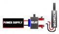
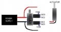
I am working on a project that uses a linear actuator. I am trying to find a module/relay or something that will change the polarity each time I plug in the power supply.
The actuator has 2 wires, the power supply has 2 wires. I just need something to put between them that will change the polarity. But I cant use anything that has a switch or button. It has to switch polarity each time I plug in the power supply.

Actuator Specs - 12DC , Full Load 12 Amps, Built in Limit Switches

I hope someone can help me out, Thank you
 

dl324

Joined Mar 30, 2015
18,222
Welcome to AAC!

Your requirements present a problem. If you can't use a mechanical switch, how is the polarity reversal circuit supposed to preserve it's state between applications of power?
 

crutschow

Joined Mar 14, 2008
38,331
You can add a small battery to power a small part of the circuit to remember the previous state.
This can be a button or coin cell if a CMOS flip-flop is used for that purpose.

If you don't want to use a battery then you will have to use a non-volatile memory device such as an EEPROM or a latching relay.
 

AlbertHall

Joined Jun 4, 2014
12,619
The only ones I could think of were an EEPROM or latching relay. A small micro with built-in EEPROM and a transistor to drive a DPDT relay would do the job and that would be my choice.

I thought it might be fairly simple to do it with a latching relay but I couldn't find a really simple way. Below is my best effort so far. R5, C1 time constant to be shorter than R6, C2 so the bistable state is defined before the latching relay changes state.
upload_2017-10-28_18-20-36.png
 

Thread Starter

xxSTIHLxx

Joined Oct 28, 2017
11
I have a Power relay, Latching single coil
http://www.newark.com/potter-brumfi...c1-12/relay-dpdt-250vac-125vdc-15a/dp/17M2962

It has 2 limit switches on it. I have no problem with using 2 power supplies, one to power the coil and one to power the actuator. But I'm not sure how to wire the 2 limit switches with only using 1 power supply, so 1 side runs the actuator out and the other limit switch runs it in. I really don't want to have to use 3 power supplies.
 

AlbertHall

Joined Jun 4, 2014
12,619
If I read it correctly, that relay will do the job on its own, running from the same 12V supply that powers the actuator - very cunning!

Is the relay that you have a 12V DC coil with DPDT switch?
 

Thread Starter

xxSTIHLxx

Joined Oct 28, 2017
11
The relay has 2 limit switches on it. When you power the coil it moves a rod to one limit switch and keeps it there until you power the coil again then it flips the rod to the other limit switch. What I don't know is how do I wire the relay to the two limit switches.

There is no DPDT switch. It just gets power when the power supply is plugged in. I don't want any DPDT switches. The power going to the coil only powers the coil to move the rod. It does not feed power to the limit switches.
 

Attachments

AlbertHall

Joined Jun 4, 2014
12,619
The two 'limit switches' constitute a DPDT switch which is what you need to reverse the polarity for the actuator.

The coil of the relay is connected to the 12V power. The two switches on the relay should be wired as below. The problem will be that the data sheet for your relay does not specify the location of the NO and NC terminals.


Thread Starter

xxSTIHLxx

Joined Oct 28, 2017
11
In my drawing, the top Limit switch from top to bottom is
COM 1
NO3
NC2
So I'm guessing the bottom limit switch would be
NC2
NO3
COM1

Im sorry, I'm not that great at reading data sheets like that. Could you please explain where the wires go?
I know 2 from the power supply go to the coil, after that I'm lost.

Also, since the power supply only powers the coil and not the Limit switches, is it possible to just split off the wires to also power the limit switches?
 

AlbertHall

Joined Jun 4, 2014
12,619
OK, looking at the pictures on the datasheet, it looks as if one switch is operated while the other isn't. therefore there is some possible confusion over NC/NO. Getting it wrong would short the power supply.

Do you have a multimeter?
 

Thread Starter

xxSTIHLxx

Joined Oct 28, 2017
11
I do not. I am just starting to get into all this relay stuff.
You are correct, one switch is powered at a time.

I did tap off of the 2 wires coming from the power supply to the coil. Which should eliminate the need for a separate power supply. If you could give me your best guess on where the rest of the wires go. I'm not worried about the power supply, I have a couple.
 

AlbertHall

Joined Jun 4, 2014
12,619
You can use the actuator to find out which terminal is which.
For now don't connect the coil of the relay.
I will refer to switch 1 and switch 2. It doesn't matter which one you call 1 or 2 as long as you are consistent.
Connect the positive wire from the supply to the COM terminal of switch 1.
Connect the negative supply wire to the COM terminal of switch 2.
These will be the final, permanent connections to the COM terminals.

Make sure the relay stays in whatever position it is (it doesn't matter which as long as it doesn't change).

Now connect the actuator between the other switch terminals as below to find which terminals supply power. You will need to try the actuator both ways round in case it is at its limit in one direction.
NC1 to NC2 (i.e. NC contact of switch 1 to NC contact of switch 2)
NC1 to NO2
NO1 to NC2
NO1 to NO2
One and only one of these should work the actuator. Tell me which and I can do you a wiring diagram.
 

Thread Starter

xxSTIHLxx

Joined Oct 28, 2017
11
Ok, when I connect
NC1 to NO2
the piston extends.

I did flip the switch by hand and it did not retract the piston.
 

AlbertHall

Joined Jun 4, 2014
12,619
OK.
Connect NC1 to NC2 and one actuator wire (doesn't matter which)
Connect NO1 to NO2 and the other actuator wire
Connect the relay coil to the supply and you're done :)
 
Top