Facebook
 Google
 GitHub
 Linkedin
OK, I am reasonably adept at soldering and such but have brain failure when it comes to understanding relays. Give me a the tools and I can swap out a clutch in a car in short order but this one has me stumped.
I have a car, 1994 Lotus Esprit S4, which I want to add remote trunk unlock to. The hatch (boot since an English car) has two large pins which are held in place when closed by spring loaded latches. The trunk is normally opened via a handle attached to a cable in the passenger compartment which unlatches both spring loaded latches. The hatch then pops up a bit by way of the struts attached to it.
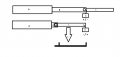
I recently installed a remote lock/unlock unit for the doors which includes a button for trunk release. What I would like to do is have a linear actuator I will mount in the boot which would pull on the spring loaded latches thus releasing the boot lid.
The remote unit works such that when the trunk release button on the remote is pressed a pulse + signal is sent. Since the pulse is obviously not long enough to power the linear actuator, and does not provide enough voltage, I got a pair of Directed Electronics 528T relays. They are DPDT relays with an adjustable timer. The timer can be set to either A. specify how long power is supplied through the relay or B. to pause for the specified time before power is sent via the relay. I also have a linear actuator which has a built in limit switch/clutch so no worries on that front.
What I envisioned, but my limited brain cell activity to make happen, is for the following to occur:
1. Trunk button on remote is pressed, which sends pulse to 528T which then sends power to the linear actuator and retracts it. After say 10 seconds, the 528T timer (adjustable via an adjustable pot) stops sending power.For this step + would be to + and - to - on the linear actuator.
2. The same pulse upon pressing trunk button is also sent to the other 528T in step 1 is sent to the other 528T and after 15 seconds (so no overlap) it sends power so the linear actuator is extended again.
Of course for step 2 the +/- sent to the linear actuator must be reversed and once the actuator has been extended again the polarity must be such that the next time the trunk release button is pressed it will repeat step 1.
Make sense?
I have looked at using microswitches, limit switches, etc. but still not getting a picture of what needs to be done, etc. Schematics I might add are not my friend at all!
THANKS!!!
I have a car, 1994 Lotus Esprit S4, which I want to add remote trunk unlock to. The hatch (boot since an English car) has two large pins which are held in place when closed by spring loaded latches. The trunk is normally opened via a handle attached to a cable in the passenger compartment which unlatches both spring loaded latches. The hatch then pops up a bit by way of the struts attached to it.
I recently installed a remote lock/unlock unit for the doors which includes a button for trunk release. What I would like to do is have a linear actuator I will mount in the boot which would pull on the spring loaded latches thus releasing the boot lid.
The remote unit works such that when the trunk release button on the remote is pressed a pulse + signal is sent. Since the pulse is obviously not long enough to power the linear actuator, and does not provide enough voltage, I got a pair of Directed Electronics 528T relays. They are DPDT relays with an adjustable timer. The timer can be set to either A. specify how long power is supplied through the relay or B. to pause for the specified time before power is sent via the relay. I also have a linear actuator which has a built in limit switch/clutch so no worries on that front.
What I envisioned, but my limited brain cell activity to make happen, is for the following to occur:
1. Trunk button on remote is pressed, which sends pulse to 528T which then sends power to the linear actuator and retracts it. After say 10 seconds, the 528T timer (adjustable via an adjustable pot) stops sending power.For this step + would be to + and - to - on the linear actuator.
2. The same pulse upon pressing trunk button is also sent to the other 528T in step 1 is sent to the other 528T and after 15 seconds (so no overlap) it sends power so the linear actuator is extended again.
Of course for step 2 the +/- sent to the linear actuator must be reversed and once the actuator has been extended again the polarity must be such that the next time the trunk release button is pressed it will repeat step 1.
Make sense?
I have looked at using microswitches, limit switches, etc. but still not getting a picture of what needs to be done, etc. Schematics I might add are not my friend at all!
THANKS!!!