OK. The 12 volt supply is also powering the relay circuit and the minus output pin of the detector is connected to minus 12 volt supply, is that correct? And if so you are reading .6 volts from minus 12 volts to + signal when idle?
OK. The 12 volt supply is also powering the relay circuit and the minus output pin of the detector is connected to minus 12 volt supply, is that correct? And if so you are reading .6 volts from minus 12 volts to + signal when idle?
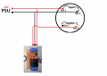
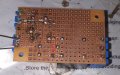
Here's how it's currently wired. In this Configuration the voltage between Det3 and Det6 reads 0.6-0.8v on idle and 12v on alarm.
If I connect Det3 to PSU ground the voltage goes to 12.6v idle or alarm.
regardless of idle or alarm, grounded or open Det3 the Det6 pin activates the relay
Here's how it's currently wired. In this Configuration the voltage between Det3 and Det6 reads 0.6-0.8v on idle and 12v on alarm.
If I connect Det3 to PSU ground the voltage goes to 12.6v idle or alarm.
regardless of idle or alarm, grounded or open Det3 the Det6 pin activates the relay
If I connect Det3 to PSU ground the voltage goes to 12.6v idle or alarm.
regardless of idle or alarm, grounded or open Det3 the Det6 pin activates the relay
if you mean one probe of the multimeter on det3/det6 and the other to ground of psu heres the values:
(Det3 and Det6 are currently both open)(black probe on psu ground and red probe on the deteptor pins)
[idle]
Det3 is 0.13v
Det6 is 12.29v
[Alarm]
Det3 is -0.7v
Det6 is still 12.29
connecting Det6 to the circuit doesn't affect the values
The thing is that the MOSFET has an almost infinitely high gate impedance at DC. Femtoamps of current will active it if the voltage is above its threshold. With the gate completely floating, waving your hand near it will cause the FET to conduct drain current.
And to make things worse, the gate structure is basically a capacitor. If an input signal charges up the capacitor and turns on the FET, then is disconnected, that open circuit capacitance can take many minutes to discharge, holding the FET in the on state.
To assure the FET is off, the gate must be pulled down to the source potential by a resistor, the action of the output stage of a driving device, etc.
I'd have to order the opto-coupler for this and tbh I dont wanna wait 5 more days for the third time for parts to arrive. do you think what you sugested in post #36 is still worth a shot? I have enough parts for that and willing to give it a go. otherwise I'm calling it quits for this project. once again I'm really grateful for your (and everyone else too!) time and effort, wish you the best!
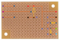
Just finished making this one and when powered the relay activates and Q1 starts heating up.
I have flipped the pic of the board so it corresponds to the diagram.
Also I found an optocoupler on an old pc psu. it is a cosmo 1010 817. can i use that instead?
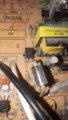
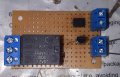
Are you sure it's wired correctly? In the first photo it appears the Source of Q2 is connected to the relay coil.
Actually appears both Q1 and Q2 are in backwards.
Are you sure it's wired correctly? In the first photo it appears the Source of Q2 is connected to the relay coil.
Actually appears both Q1 and Q2 are in backwards.
ok so i tried this one too but the mosfet just lets current through. I even disconected the opto to rule out the possibility of it being faulty to no avail. I dont get it, it's the same path as the circuit on post #14 which didn't let current through normally but here it activates when powered by psu. Replacing the mosfet didn't change the behavior as well.
Will need to see photos. Make sure they are not reverse images.
Circuit should look this without the opto. Voltage on the gate should read 0 volts and 12 volts on the drain. Negative or common lead of the meter connects to -12 volts.
Will need to see photos. Make sure they are not reverse images.
Circuit should look this without the opto. Voltage on the gate should read 0 volts and 12 volts on the drain. Negative or common lead of the meter connects to -12 volts. View attachment 300272
I'm reading 2.34 volts both on drain and gate; so I'm assuming the mosfet has failed.
pins 3 and 4 of opto with negative probe on 3 read 0.41v, the diode reads -9.9v one way and 10.2v the other.
Edit: i'm heating up my iron to disconnect the opto and remeasure. will edit once done.
It measured the same 2.34v on both Drain and Gate to ground
 Facebook
 Google
 GitHub
 Linkedin