12 V, 10A regulator

Thread Starter

Rut

Joined Dec 11, 2014
5
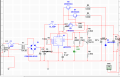
Hello, I need some help. I have to make a simulation for this circuit but something is wrong. I have created it with multisim but I do not get the ringht output. Maybe someone can help me to create the right one circuit on multisim?
 

Attachments

LDC3

Joined Apr 27, 2013
924
I looked up a datasheet for a LM723, but could not find one that matched the same pin output as the one used in the circuit so I don't know which pin is for what.
What does surprise me is that there are 3 resistors connected betweens pin 4 and 10. Either there is an error on the circuit, or parts of the circuit were added on after it was tested. I don't know what R4 is meant to do.
I believe that R3 is mis-wired and should not be connected to pin 4; which means you can move it parallel to the 15V zener diode. It makes sense having it here since it indicates when the output is ready and R3 limits the current to 20mA. If R3 is not mis-wired, there there will be 23mA flowing through LED1.
There may still be a problem since I don't have access to multisim.
 
Top