 Facebook
 Google
 GitHub
 Linkedin
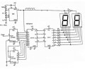
hi guys i need help
I made the circuit in schematic again and again but it doesnt count.
i use 10uF instead of 1uF and I took the wave I wanted .
I dont know where to put the 5th entry (CLCK)on 74192 i try the 1, 0, and 3th entry on 555(Pulse output ) but it doesnt work.
I wanted to ask if there is a problem I cant notice.
Attachments
-
 161 KB Views: 37


