Input Circuit For A 0 To 30 MHz Frequency Counter

Status
Not open for further replies.

Thread Starter

NapSolo

Joined Oct 29, 2024
115
Hi

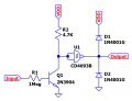
I built a 0 to 30 MHz frequency counter and I am wondering what kind of input circuit would be
required. The circuit has two range settings, 0 to 1MHz and > 1 MHz to 30 MHz. The signal to be
measured feeds a CD4510 counter if it is 0 to 1 MHz or a 74HC390 if the signal is >1 MHZ to 30 MHz.

I am currently testing the circuit using an arbitrary waveform generator. I can successfully read sine,
ramp and square waves. The generator outputs good quality signals but I am concerned about the
signals that might be measured on the bench. Also, does an input circuit need to provide protection
from voltages higher than the 5 volt system voltage and also current levels.

Any suggestions would be greatly appreciated.

Thanks!
 

Thread Starter

NapSolo

Joined Oct 29, 2024
115
What kind of input circuit you need depends on what it is driving - the input of the CD4510 and 74HC7930 (switchable?)?

These might help:
To > 100 MHz:
View attachment 342377

To 30 MHz:
View attachment 342378
Thanks Dick. This is the prescaler. The select will be a high or low level supplied
by a debounced switch, although I was trying to make the prescaler automatic
but the carry out on the MSD CD4510BE would not do the trick.
 

Attachments

Thread Starter

NapSolo

Joined Oct 29, 2024
115
What amplitude input sensitivity do you want?
Hi

The signal amplitude should be 5 volts. The supply voltage is 5. Not sure about the sensitivity. I would
like to use the counter to measure both audio frequencies and rf frequencies when experimenting
with circuits as a learning process. I hope that clarifies what might be needed.

I suppose there needs to be some sort of overload protection so I don't blow the thing up.

Thanks
 

DickCappels

Joined Aug 21, 2008
10,661
This confirms that you need protection against input voltage swings that might otherwise damage the input circuitry.

The resistor followed by clamp diodes to Vcc and Ground are probably a very good bet. Just realize that the resistor and the capacitance of the two diodes forms a low pass filter so it is necessary to keep the attenuation from this effect from making the highest frequency signals too small to be reliably detected.
 

Thread Starter

NapSolo

Joined Oct 29, 2024
115
This confirms that you need protection against input voltage swings that might otherwise damage the input circuitry.

The resistor followed by clamp diodes to Vcc and Ground are probably a very good bet. Just realize that the resistor and the capacitance of the two diodes forms a low pass filter so it is necessary to keep the attenuation from this effect from making the highest frequency signals too small to be reliably detected.
Here is a circuit that I constructed using Spice. It appears to work in the simulation but will it work in
the real world? If it will work, what wattages of resistors and zeners might I need, assuming that the
highest input voltage could be 100 volts.

ThanksOverload Protection And Signal Conditioning Circuit.pngOverload Protection And Signal Conditioning Circuit.png
 

MrChips

Joined Oct 2, 2009
34,628
R1 value is too high. Q1 base is not properly biased.
You would be better off to feed the signal directly into the input of U1 via a 1k Ω resistor and no pull-up.
 

AnalogKid

Joined Aug 1, 2013
12,043
If the input circuit is running on 5 V, consider a 74AC14 or 74AC132. The AC and ACT series are a very fast and well-behaved CMOS family, and the spare gates can be used for other logic functions.

ak
 

Thread Starter

NapSolo

Joined Oct 29, 2024
115
R1 value is too high. Q1 base is not properly biased.
You would be better off to feed the signal directly into the input of U1 via a 1k Ω resistor and no pull-up.
What is wrong with the biasing. Is this going to protect the counter if 100 volts suddenly appears on
the input? No transistor?
 

Thread Starter

NapSolo

Joined Oct 29, 2024
115
Where is my schematic?
R1 value is too high. Q1 base is not properly biased.
You would be better off to feed the signal directly into the input of U1 via a 1k Ω resistor and no pull-up.
I want to protect the frequency counter input so that the maximum input is 5 volts at a frequency up to
30 MHz. Is this circuit any good? If not what changes would be required?

ThanksOverload Protection And Signal Conditioning Circuit.png
 

WBahn

Joined Mar 31, 2012
32,703
Where is my schematic?

I want to protect the frequency counter input so that the maximum input is 5 volts at a frequency up to
30 MHz. Is this circuit any good? If not what changes would be required?

ThanksView attachment 342861
Assuming that the output of your conditioning circuit is what is being applied to the input of the frequency counter, then the output is already limited to the power supply rails of what ever is powering your CD4093B.

If you are wanting to clamp your input to the circuit, use regular diodes, not zeners. The zeners will allow the voltage at the base of the transistor (ignoring the clamping effect of Q1 for a moment) to go between -5.1 V and Vdd+5.1 V. But the transistor itself will clamp that node to no more than about 0.7 V.

If you want to use diodes to clamp the output of that circuit, then use diodes at the output of the circuit. Normal, or Schottky, diodes.
 

Thread Starter

NapSolo

Joined Oct 29, 2024
115
Assuming that the output of your conditioning circuit is what is being applied to the input of the frequency counter, then the output is already limited to the power supply rails of what ever is powering your CD4093B.

If you are wanting to clamp your input to the circuit, use regular diodes, not zeners. The zeners will allow the voltage at the base of the transistor (ignoring the clamping effect of Q1 for a moment) to go between -5.1 V and Vdd+5.1 V. But the transistor itself will clamp that node to no more than about 0.7 V.

If you want to use diodes to clamp the output of that circuit, then use diodes at the output of the circuit. Normal, or Schottky, diodes.
Thanks WBahn. Revised schematic attached. Is a 1 Meg resistor too high?
 

Attachments

MrChips

Joined Oct 2, 2009
34,628
Replace the diodes D1 and D2 with ordinary small signal diodes. You don't need Q1. Connect directly to U1.
Yes, 1M Ω is too high. Use 1k Ω.
 

WBahn

Joined Mar 31, 2012
32,703
Replace the diodes D1 and D2 with ordinary small signal diodes. You don't need Q1. Connect directly to U1.
If he connects directly to Q1, he is left with a signal inversion. But this is better met by just using another one of the inverters in the 4093, assuming one is available.
 

WBahn

Joined Mar 31, 2012
32,703
Thanks WBahn. Revised schematic attached. Is a 1 Meg resistor too high?
Yes. Assuming you choose to use a transistor inverter, you will want something smaller. How small depends on what you are driving it with. Since you want this to work at up to 30 MHz, you need to properly analyze that inverter to see how it will perform at that frequency. Better to just use two inverters from the 4093 in series.
 
Status
Not open for further replies.
Top