troubleshooting a tv power supply

Thread Starter

johndoe45

Joined Jan 30, 2010
364
hello

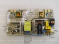
i was just wondering the steps to troubleshooting a power supply

i have checked all the capacitors already.

the problem started when i accidentally forgot to unplug the power supply and touched the circuit board with a probe not grounded and made a small spark.

i read somewhere that if the inductor has failed and needs to be replaced. the power supply will be inoperable.

the fuse keeps blowing every time i replace it which was just twice. i can't take voltage readings cause the fuse is in the very front. how do i test the power supply when the fuse keeps blowing????
 

Attachments

Last edited:

Thread Starter

johndoe45

Joined Jan 30, 2010
364
thanks bertus. I've actually came across that website one time. It is an INSIGNIA NS-LTDVD19 tv. It is a switch mode power supply I'm pretty sure.

My question was how to test the power supply when I can't get a voltage across the fuse part that keeps blowing????
Is a continuity test the only thing I have and trial and error desoldering and testing components one by one????
 
Last edited:

bertus

Joined Apr 5, 2008
22,278
Hello,

It could be there is a short in the switching transistor.
It is located on the thin alumunium hook near the large black capacitor.

Greetings,
Bertus
 

Thread Starter

johndoe45

Joined Jan 30, 2010
364
i think i already tested both of those as well

there is like a base, emitter, and collector.

"With the meter set to measure ohms, clip one meter lead to the base connection of the transistor.
Touch
the other lead first onto the collector lead and then onto the emitter lead.
The readings should both be the same, either both high resistance or both low resistance. Now reverse the leads and repeat the procedure.
The results should be the opposite of those obtained before.
If they were both high before they should now be both low.
If they were both low before they should now both be high.
Now measure the resistance between emitter and collector.
It should read high resistance in both directions."


after doing this both switching transistors were ok with this test. but putting it in a circuit would probably be better, right???? so i would need a variable power supply and resistance box and a LED?
 

R!f@@

Joined Apr 2, 2009
9,918
It seems to me that board has the SMPS and the CCFL Inverter.
Have you got it fixed.
If not and if you want to fix it PM me.
 

R!f@@

Joined Apr 2, 2009
9,918
We are having a thunder shower right now, and my connection keeps resetting.
I am here even though I might appear offline
 

Thread Starter

johndoe45

Joined Jan 30, 2010
364
here are two pictures

burn marks on the input source is because i got frustrated and connected two terminals cause thought no power was coming in at all. soldered it all back though. : )

thanks for all your help so far Rifaa
 

Attachments

Last edited:

R!f@@

Joined Apr 2, 2009
9,918
See the picture.
I have marked two components.
I want you to desolder them carefully.
Remember to desolder the heatsink too.
Give me the no. of the transistor and check the bridge for a shorted diode.
Post the results and pictures of that area closeup with better lighting.
 

Attachments

Thread Starter

johndoe45

Joined Jan 30, 2010
364
i'm not home right now. i will desolder them tonight and test for the diode in the bridge rectifier. now my DMM Fluke 117 has a diode function and is supposed to beep once if right. but if it doesn't beep but has a different value over the range does that mean it is shorted. i've desoldered the bridge rectifier before. can tell from the picture. why don't you just look at my first post. its the same board. tested the resistors and nothing looks burned.

attached is the first pic in the first post
and i will not be able to get you an actual picture until tomorrow. picture was taken out in the sun. flash is too bright. and by time i get home it will be dark.

P.S. desolder the heat sink? mean that metal half rectangle that the transistor is attached to? i can just screw it off with phillips then desolder the transistor.

and one quick question. the inductor after the input source (what do you call that EMF?) has some black stuff in it. I read its like glue or something. I don't know. I will take a side angle of it and get clearer shot of the part that you can't see asap.

Thanks for your help. Tried asking people at school but wouldn't help me learn how to troubleshoot circuits.
 

Attachments

Last edited:

R!f@@

Joined Apr 2, 2009
9,918
U said you are blowing fuses, so I need to check for shorts.
If you can remove the transistor easily then do it.
Do you know how to check FET's and Bridges.
For now remove them and check for zero resistance from pin to pins
 

Thread Starter

johndoe45

Joined Jan 30, 2010
364
i will do that when i get home. i don't think i have the equipment for that.

the bridge rectifier i know i can use the diode test and supposed to beep once one way and not beep the other way. and on the other side i forgot

FET is supposed to be high resistance both ways. Then switch polarity and low resistance both ways. Then I forgot what else.

would be nice if you could explain in detail. Cause there are so many ways you can test these things that I have no idea what to do.

been researching about it for quite awhile. so i have some idea of what to do.
 

R!f@@

Joined Apr 2, 2009
9,918
OK . I'll draw up diagram on how to check those components, meanwhile desolder them.
and also post the component no.s too
 

Thread Starter

johndoe45

Joined Jan 30, 2010
364
here is the photo and both are soldered out. is the bridge rectifier temperature sensitive because took me awhile to wiggle that one out. my solder gun is just a cheap one from radioshack so doesn't get as hot as most.

2nd picture is blurry. but it was just to show you that glue or black stuff in inductor. don't know what it is????


Part No's
Transistor - K2843
Rectifier - KBP206

okay. i tested the bridge rectifier with the diode function (supplies only up to 2.0V which might not be sufficient enough?). researched up a bit. it beeped in four different positions and didn't conduct the opposite way. so that one is good i think.

same thing with the transistor. i connected the base and the emitter and it beeped. switched polarity and it didn't beep. so that side was good. then went to collector and base. didn't beep either way which should mean it is BLOWN!!!! then did collector and emitter and didn't beep either way.

but this could have been done due to overheating like i said. so is the transistor blown from what i stated????

i have the basic radioshack soldering iron. takes forever to heat up and debraiding solder wick sucks because not enough heat to keep solder in the liquid state. so continuous heating until it falls out. usually pry it while going from pin to pin but this can get frustrating especially for a bridge rectifier with four pins when it takes time to make solid solder a liquid (with low heat solder gun) then solidifies so fast. is there a faster way to get these things out that i don't know???
 

Attachments

Last edited:
Top