
 Facebook
 Google
 GitHub
 Linkedin
Blog entries by Artbyrobot
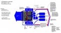
Ok so I realized I don't have to feed in 8v+ from an external wire when I can just pull it from a neighboring pin on the chip that has 8v+ already fed to it from one of the big 8v+ copper traces attached to one of the big 8v+ pads on the underside that connect directly to one of the side pins...
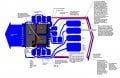
Ok so I was thinking now that each half bridge is just a tiny IC rather than a pair of hefty power mosfets, the space taken up overall by my entire bldc motor controller is going to be about 3cm x 1cm x 2mm which is insanely small for 30a continuous at 8v motor controller! This realization...
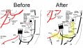
OK, so when I was thinking of using both my discrete components motor controller design parts I already made and then also separately implementing the integrated half bridge IC design going forward, it hit me that the 8v- and arduino gnd tie together on the half bridge IC by necessity but this...
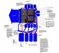
Well I deep dove into the CSD95481RWJ IC route. I estimate it will cut the work in half roughly for every motor controller made and cut the size taken up by about 60% compared to my previous discrete components approach.
Now I will note that I did come across the BTN8982TA which is rated to 40v...
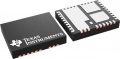
I was randomly talking to chatgpt about how I have been feeling burdened by having to make my own BLDC motor controllers for my robot lately and it randomly mentioned integrated half-bridge power modules as something I could use to cut down on my labor load in making these motor controllers...
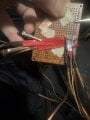
So I did manage to add a pair of braided solder wick wire as a added layer over the nickel strips of the highside mosfet setup and I insulated that with red electrical tape folded over it. I also insulated everything else in sight for the most part. I lost the original control circuit so I made...
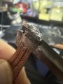
I used my jumbo Weller W100P soldering iron to attach my 6 solder wick braids to the back of the highside mosfet today and it attached instantly without a hitch. I used low temp solder paste liberally between the two on both surfaces then with my left hand smashed then together with the tip of a...
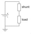
I did some research of some loose ends today on chatgpt and discovered that my .1mm x 4mm x 60mm sections of nickel strip on my bldc motor controllers that run from the battery to the motor controller mosfets and from the mosfets out to the motor are too high in resistance and at 30a they would...
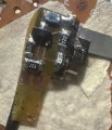
Ok here's the populated board. I tested it with 5v positive and ground and the LED came on so it is for sure not shorting and has continuity so is most likely all working. The next test will be the full low-side switch with this board acting as the drive of the main mosfet for the switch. And...
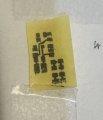
I successfully made a viable flex pcb on my second attempt.
I started by printing the circuit onto a mailing envelope using my laser printer. Then I taped a piece of toner transfer paper for pcbs shiny side up directly over where the print on the envelope was. This way I could use just a tiny...
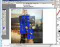
So armed with my successful electronic test of my prototype highside switch with driving circuit all passing, I determined now it is sufficiently validated to go through the process of converting it into a printable schematic and doing the whole DIY flat flex PCB making and acid etching process...
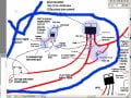
I just tested the positive high-side switch portion of the motor controller and everything seems to be working as intended. The section including all parts involved is circled in a bold blue line to indicate the portion I just tested successfully.
One issue I'm having though is that the drain...
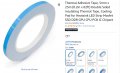
Here's the thermal tape I bought for mosfet heat sinking off Amazon:

Okay so here I have attached the LED and resistor pair with their 30ga wire wrapping wire onto my highside mosfet's front face. I may add conductive silver paste to the wire wraps in the future if any issues come up there. However, I am wondering if just tightly wrapping it in electrical tape...
Couple updates:
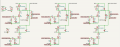
An audience member redid my brushless DC motor schematic in the traditional commonplace formatting which for most is easier/quicker to read and understand due to familiarity. So I'm reposting it. It looks mostly accurate although I have since added a 100nF ceramic capacitor...
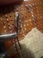
Ok so I decided to use 30 gauge wire wrapping wire and wire wrap that onto my nickel strips that I connected onto my LED setup then trim off any excess nickel strip. What I like about this is this wire is very fine so it takes up hardly any space and by being able to wrap it on I did not have to...
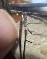
Well I finally got back to the electronics after about a month long detour real life interruption. All kinds of stuff slowed my progress on this session. But I got stuff done nonetheless. 0603 LED to 0805 resistor and some nickel strip leads coming off. Tested and working. This will be the...
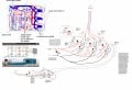
I started some testing on some subsections of the BLDC motor controller and ran into some problems and learned several things. I'm working with chatgpt to resolve each issue and have been updating my schematic to reflect alot of the changes I am making. One thing I learned is that for the high...
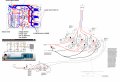
Back on the electronics again. Have been going over my BLDC motor schematic and making some little tweaks to it. Here's the updated schematic. It's a combination of lots of other schematics I've found online as well as some chatgpt help. With 1 being no clue and 10 being absolute expert tier in...
I installed two tensioners for the robot and they were seriously successful overall in testing. So much so that I am now confident enough in the entire pulley system to move onto the custom mini BLDC motor controller to get the motor to run motorized tests of finger movements next. Well after a...
