 Facebook
 Google
 GitHub
 Linkedin
Blog entries by Artbyrobot
I soldered on the rest of the SMD components. I noticed the PCB peeled back off the chip in one corner though so I plan to use kapton tape to tape off everything but that corner, use a couple alligator clips to pinch the PCB onto the chip tightly so it can't move, and then use hot air from a...

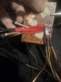
I wanted to be able to get in there and test this board for shorts and check all traces for continuity with my multimeter but felt its leads were too big for this tiny of a board setup. So I came up with this idea to use alligator jumper cables to attach sewing needles to the multimeter probes...
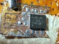
Ok so I had multiple failed attempts to solder the chip on. Despite pretinning the PCB, on both attempts when the solder went molten the chip did not center itself and lock into place as would be expected but instead slid out of position significantly both attempts. After the first attempt I...
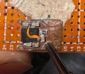
Ok I managed to apply the UV solder mask today and it seems like it worked quite smoothly. I used the tip of a small sewing needle to spread it over the trace and then held the UV light on it for 10 seconds to play it safe. I used transparent UV solder mask so you can still see the trace but its...
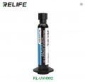
Ok so the Relife RL-UVH902 UV fast cure solder mask order has arrived and so has my order for a Relife UV curing light to cure the solder mask quickly and effectively. So now I just need to solder mask off that little trace that goes under the half bridge IC chip.
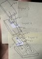
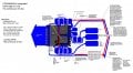
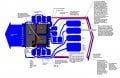
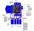
So the plan I have for the heat sinking main conductors that attach to the bottom pads of the IC chip I decided to draw up to explain it. It will be in layers. First you have the chip on the bottom facing bottom side up so the pads are exposed upwards. Then on the first attachment layer I cut...
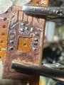
Ok I used the tip of my exacto knife to carefully scoop on low temp solder paste and then carefully drag soldered it over the key areas I wanted pre-tinned. There do not appear to be any short circuits and the amount of solder on each pad and trace seems a decent amount to me. I forgot to wipe...
So as I fast approach motor controller wiring phase, I figured I would revisit placement again. Upon further reflection I decided hovering midair motor controllers attached to nothing might not work as they'd perhaps be a bit in the way of getting at the motors and just be a bit overwhelming...
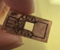
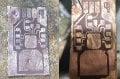
Here's the center cutout now which was the last thing I needed to do before soldering down the chip. This access window will enable me to solder the main power lines to the main pads on the bottom of the chip. The circuitboard is aimed at tying into the various perimeter pins of the chip but...
I got together my temperature sensor and my hot plate and my glass container and some water and figured out where on the hotplate temp dial I need to be to get the desired water temperature. I then used label paper sticker and marked it off and wrote 118f on it which is the average temperature...

Ok so I created what I'm calling the Orchestrator.py, a python code a couple thousand lines long that interfaces with chatgpt, being able to go into my codebase for chatgpt and pull sections of code out and populate my clipboard with that code and ask me to paste it in for chatgpt which I then...

So I was randomly watching YouTube recently and saw a George Hotz past broadcast entitled "George Hotz | Programming | Welcome to Gas Town and the future of Computer Use | Agentic AI | Part 1". It kind of shocked me to see this. I was under the impression for some years now that vibecoding was...

So I ran into some issues trying to make the DIY flex PCB for my integrated half bridge IC chip. This chip has extremely fine 0.4mm pin spacing so the PCB has to be insanely accurate. My previous discrete components BLDC motor controller variant enabled me to create much more crude and less...
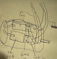
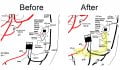
Ok so I realized I don't have to feed in 8v+ from an external wire when I can just pull it from a neighboring pin on the chip that has 8v+ already fed to it from one of the big 8v+ copper traces attached to one of the big 8v+ pads on the underside that connect directly to one of the side pins...
Ok so I was thinking now that each half bridge is just a tiny IC rather than a pair of hefty power mosfets, the space taken up overall by my entire bldc motor controller is going to be about 3cm x 1cm x 2mm which is insanely small for 30a continuous at 8v motor controller! This realization...
OK, so when I was thinking of using both my discrete components motor controller design parts I already made and then also separately implementing the integrated half bridge IC design going forward, it hit me that the 8v- and arduino gnd tie together on the half bridge IC by necessity but this...
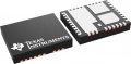
Well I deep dove into the CSD95481RWJ IC route. I estimate it will cut the work in half roughly for every motor controller made and cut the size taken up by about 60% compared to my previous discrete components approach.
Now I will note that I did come across the BTN8982TA which is rated to 40v...
I was randomly talking to chatgpt about how I have been feeling burdened by having to make my own BLDC motor controllers for my robot lately and it randomly mentioned integrated half-bridge power modules as something I could use to cut down on my labor load in making these motor controllers...
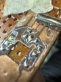
So I did manage to add a pair of braided solder wick wire as a added layer over the nickel strips of the highside mosfet setup and I insulated that with red electrical tape folded over it. I also insulated everything else in sight for the most part. I lost the original control circuit so I made...
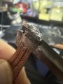
I used my jumbo Weller W100P soldering iron to attach my 6 solder wick braids to the back of the highside mosfet today and it attached instantly without a hitch. I used low temp solder paste liberally between the two on both surfaces then with my left hand smashed then together with the tip of a...