 Facebook
 Google
 GitHub
 Linkedin
Blogs
The Equivalent Circuit of Zener diode Using Diode and LED Protection.
The circuits are using to explain for someone how a Zener diode work when using diodes, it's more easy to understand, and I hope these can help you some more.
Introduction
Let's set the stage for this discussion by defining a function with the following truth table.
#||A|B|C||F
0||0|0|0||0
1||0|0|1||1
2||0|1|0||0
3||0|1|1||1
4||1|0|0||1
5||1|0|1||0
6||1|1|0||1
7||1|1|1||1
Table 1 - Arbitrary function defined via Truth Table
The first column is...

Tracecom and I got together on this. I designed it, he built it, he says it works.
The Max6035 chip in 1/2% accuracy is used as a stable 10.00 ma current source. The rest is calibration and a Kelvin connection.
The 200 mv scale on a DVM will show 199.9 while indicating 19.99 ohms. Good for...
The complex power of a circuit in sinusoidal steady state is defined as
(1) \ \overline{S} \, = \, P \, + \, jQ
where P is the real power and Q is the reactive power given by
(2) \ P \, = \, V_{eff} \cdot I_{eff} \, \cos(\Theta_{vi})
\
(3) \ Q \, = \, V_{eff} \cdot I_{eff} \...

Low Temperature Drift jfet Constant Current Circuit
You can almost see by looking at the transfer curves of a typical jfet that all the curves for various temperatures cross at a point. My point here is that they really do cross at a point.
Any particular part number for a jfet will have a...

This circuit was prompted by the following thread
http://forum.allaboutcircuits.com/showthread.php?t=88409
in which the OP wanted to know how to choose the resistor values by design instead of by happening (i.e., trial and error).
I figured it might be useful as a general example, and so put...

Let's use the following circuit.
Ideal Opamp Approximations
We will use the following three assertions based on the assumption that we are working with an ideal opamp:
1) No current flows into either input.
2) The output is an ideal voltage source.
3) The configuration is consistent with...
Annoyed by the inaccuracy of people saying, "It takes six tenths of a volt to turn a transistor on", I did a graph of a bipolar transistor (2N4250A) to see what happened. The graph shows an almost perfect straight line from 1na to 1 ma on a lin/log graph. (I quit at 1 ma to avoid heating the...
I was postponing this post until I got a chance to acquire and test a 2x20 3V LCD.
I have not gotten one as yet so the test will have to wait.
I wanted the display to show the date and time like this:
However, when Wednesday comes around, I need 18 characters across, hence the need for a...
SRF(Self-resonant frequency)
The frequency at which the inductor's distributed capacitance resonateds with the inductance, it is at this frequency that the inductance is equal to the capacitance and they cancell each other, the inductore will act purely resistive with a high impedance at the SRF...
Saturation Current
The DC bias current flowing through the inductor which causes the inductance to drop by a specified amount from the initial zero DC bias inductance value , common specified inductance drop percentages include 10% and 20%.it is useful to use the 10% inductance drop value for...
Here is a 24-hr Clock/Calendar project with a twist.
The idea is to create a perpetual clock that will run for 10,000 years without requiring calibration. This idea was inspired by the 10,000 Year Clock project from the Long Now Foundation:
http://longnow.org/clock/
To achieve this goal, I...
You can use your handheld TV remote controller to turn on/off lights, appliances, gadgets, robots, etc.
Here I will show you how you can receive and decode the infra-red (IR) signals transmitted by the controller. This is also an excellent exercise to learn and use the intricate functions of...
Here is my MSP430G2553 LCD Terminal program.
Where would I use something like this?
1) If I am debugging a system and would like to see some internal results I can send ASCII text to a dumb terminal. Can I not use the IDE debugger to trace the code? Many times I am debugging in "real time" and...
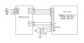
Here is the MSP430G2553 to LCD example, test setup, circuit diagram and program.
//************************************************
// MSP430 - LCD Test Program
//************************************************
/************************************************
2013.06.22 - MrChips...
Sometimes when I am developing and debugging a system I need to monitor some intermediate result. I do this by sending ASCII text serially to a "dumb terminal" such as HyperTerm. Believe me, I have a PC on my workbench running COMM on MSDOS just for this purpose.
I also have a microcontroller...
Now that we have verified that the ADC is configured properly and working, we can connect the LM35 and then look at the numbers.
Connect the LM35 to Vcc and GND of the MSP430G2553. Connect Vout from the LM35 to P1.7 (pin-15) of the MSP430G2553.
It is educational to look at the math.
The LM35...
Now that we have three digits being displayed, what can we do with them?
The first project that comes to mind is a digital thermometer. We will use the popular LM35 temperature sensor which outputs an increasing voltage as the temperature rises. The transfer function of the LM35 is a linear...