Facebook
 Google
 GitHub
 Linkedin
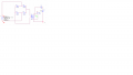
Look at the specs for the 4N25. You will see that the absolute maximum reverse voltage is 5 V. Assuming no leakage current, you are asking it to withstand over 320 V reverse. You've likely destroyed the 4N25, although the 22 kΩ resistor might have limited the current to a survivable level.Hey guys, i'm trying to do zero crossing with the 4n25 but to no avail. Here's the circuit:
For the bridge i'm using four 1N4001 diodes, and i'm trying to see the output signal with an oscilloscope. Any ideas?
thanks
Put a zener diode (somewhere in the 3 V range) in anti-parallel with the LED to clamp the reverse voltage.
If you are using 1N4001 diodes, then you are likely damaging them, as well since they are only rated for 50 V peak reverse voltage. Look at using 1N4007 diodes.