170mV at the collector output with respect to ground suggests that the transistor is turned on.
Check to make sure that the 5VDC source and the 10kΩ collector load resistor are both correct.
1.17V across the emitter diode is not high enough to turn on the LED.
Check that the 4N35 is either busted or you have the wrong pins connected.
Just a thought:
You might be asking a lot more from that isolator than it is capable of delivering.
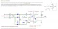
The output of the bridge will be below 1.3 V for about 20 us (assuming 120 VAC @ 60 Hz). The 4N25 has rise and fall times of 2 us with a 100 ohm load at 10 ma (5V power supply) but your circuit has a load 100X that for which the 2 us is specified . It might be that the transistor never turns off because the base voltage does not go low long enough for it to do so.
Putting a resistor of 100k across the LED will increase this time and give the transistor a chance to turn off.
Ericgibbs's suggestion of putting a 10k resistor across the base and emitter is a good idea since that will speed up the turn-off of the transistor (the minority carriers need to get out of the junction somehow).
First off get a new 4n25 you probably blown the led in it. Maybe not But i've done it before and led died I changed to the part 4N35 But the 4n25 never worked after.
A lot of more recent opto's don't have base pins - these days, most are 4 pin package like the motor drive MOSFETs on early HDDs.
Most mains isolation optos in DIP-6 package have all their pins, but no internal connection to base.
Probably pointed out a dozen times already - but those 4001s probably failed instantly and opened the resistor. 4007 is the least that should be used.
There are off the shelf opto's with built in ZC circuitry. I'd do it at low voltage from the secondary of a transformer. If the rectifier feeds a reservoir cap, an extra diode is needed to isolate the rectifier from the reservoir. The rectifier will be raw DC without being kept up by the reservoir.
If the transformer is giving mains isolation - you can just detect the zero crossing points with the B/E junction of a transistor, via a current limiting resistor.
 Facebook
 Google
 GitHub
 Linkedin