Zener diode_reverse bias

Ian0

Joined Aug 7, 2020
13,132
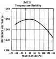
Zeners around 6 to 7 Volts have zero temperature coefficient as the Zener effects and Avalanche effects have opposite temperature coefficients, and they cancel out at around 6V. That doesn't mean to say that the voltage of zener in that region is particularly accurate, just that it stays at the same inaccurate voltage as the temperature changes!
 

Audioguru again

Joined Oct 21, 2019
6,826
Almost all my Lithium rechargeable battery powered products except one have an accurate and proper charger circuit.
A little portable vacuum cleaner was found with a dead Ni-cad battery so I used two 18650 Lithium cells from an old laptop.
I used an adjustable LM317 voltage regulator set to exactly 8.40V and the wall-wart limits the charging current to 500mA. It charges overnight.

I would never use a zener diode to produce an accurate voltage, even a "A" version voltage is within 5%.
 

MrAl

Joined Jun 17, 2014
13,704
Almost all my Lithium rechargeable battery powered products except one have an accurate and proper charger circuit.
A little portable vacuum cleaner was found with a dead Ni-cad battery so I used two 18650 Lithium cells from an old laptop.
I used an adjustable LM317 voltage regulator set to exactly 8.40V and the wall-wart limits the charging current to 500mA. It charges overnight.

I would never use a zener diode to produce an accurate voltage, even a "A" version voltage is within 5%.
Hi,

Yeah i found several cheap China made units with zeners for the reference. Not a good idea.

The LM317 works ok as long as the current is not too high. If the current goes higher we have to keep an eye on the voltage regulation change because it is higher than expected. When we look at the data sheet, we see a typical reference diode curve, but when the series pass element that handles all the current gets hot, so does the reference, and that makes it change in voltage. So although the reference follows the curve given in the data sheet, the thermal feedback from the pass element changes all that when it gets hot because then the ambient temperature is not the only factor for temperature to consider when computing the projected change in reference voltage. The ultimate change is much more than expected for a voltage regulator IC. Now run it at low current and there is no problem because then the series pass element stays relatively cool and so mostly only the ambient temperature affects the voltage reference part of the IC chip. The overall response with higher current is very very surprising and unexpected because it says nothing about that on the data sheet, or at least it didnt (it may show up there now or soon).

Of course this problem shows up with other regulators too similar to the LM317 and most likely any regulator that has both the reference diode and the series pass transistor on the same die or maybe even in the same package, and of course if the heat from any heatsink in any product is not mitigated properly then there is still a possibility of thermal feedback to the reference IC.
So the question becomes not only does the reference diode possess a decent temperature profile but also does the product itself somehow heat up the reference diode.
 

crutschow

Joined Mar 14, 2008
38,511
The overall response with higher current is very very surprising and unexpected because it says nothing about that on the data sheet
Well, the data sheet shows the reference voltage variation versus junction temperature, so the variation with power dissipated would seem to be implied.
 

MrAl

Joined Jun 17, 2014
13,704
Well, the data sheet shows the reference voltage variation versus junction temperature, so the variation with power dissipated would seem to be implied.
I dont see how since it depends on temperature not power. Although temperature depends on power, it also depends on heatsinking (i.e. heat removal). So there is no direct correlation.
But even if so it is not something that is usually thought about probably because there is no direct calculation for that variation even though that data might be given. Once someone mentions it however then it becomes very apparent.

It is interesting to think about a 12 volt DC output application with say 1 amp current and some input like 15 volts (or something) and different heat sinks. Even with a decent heat sink we see a change in output voltage that is much larger than we would expect to see given any voltage reference diode based regulator as the chip heats up. Take the diode off die however and we see much better behavior . For an Li-ion based application it could possibly take it beyond the recommended max voltage for the cell (i looked into this several years ago but i'd have to look up my notes to see what the results were). The overall conclusion was for a really stable power supply it is better to use a separate voltage reference that is not subject to power heating.
 

MrAl

Joined Jun 17, 2014
13,704
The datasheet if an LM317 shows that it has good thermal stability of its reference voltage.
Yeah but "good" is a relative term. We need numbers to know anything real.
It is good relative to a zener diode, but not so good relative to an off die separate voltage reference. This is why i always say the specs are misleading.

But also the reference voltage alone has "very good" thermal stability, but when coupled with the power handling series pass element the stability not only depends on ambient temperature but also on the heating from the pass element. That makes it appear much less stable than the reference voltage stability. In other words, the output at say 12 volts changes much more than the reference diode and ambient temperature would suggest and that is simply because it depends on the internal heating as well as the ambient temperature.

An analogy might be to create two 12 volt voltage regulator circuits with a separate voltage reference diode (not internal with the pass element). Then power up and check the output voltages. Then heat one reference diode up with a soldering iron to maybe 80 C and see how much that one changes output voltage. The one that gets heated of course changes a lot more than the one that doesnt get heated. In the LM317 and similar, the reference diode gets heated by the series pass element heating as the output current rises and that causes a similar effect.
The effect is much more than we might expect.

I have some data on this i''ll have to try to find it.
 

Ian0

Joined Aug 7, 2020
13,132
Is it just a coincidence that the uA723 and a lot of other ICs of its age have zeners which just happen to be the same voltage at which transistor base-emitter junctions break down?
 

Audioguru again

Joined Oct 21, 2019
6,826
The schematic of the LM317 in its datasheet shows a 6V zener diode and a 6.3V zener diode. Datasheets of zener diodes show them to be thermally stable.
A graph of the LM317 thermal stability shows its reference voltage dropping 0.04% when its temperature drops from 25 degrees C to -50 degrees C and shows its reference voltage dropping 1% when its temperature increases from 25 degrees C to the max allowed temperature of its chip at 125 degrees C.
Pretty darn good.
 

Attachments

MrAl

Joined Jun 17, 2014
13,704
The schematic of the LM317 in its datasheet shows a 6V zener diode and a 6.3V zener diode. Datasheets of zener diodes show them to be thermally stable.
A graph of the LM317 thermal stability shows its reference voltage dropping 0.04% when its temperature drops from 25 degrees C to -50 degrees C and shows its reference voltage dropping 1% when its temperature increases from 25 degrees C to the max allowed temperature of its chip at 125 degrees C.
Pretty darn good.
Yes 1 percent isnt bad at all for many applications. It's all about the type of application though.

Try building a precision bench power supply from one of these and you will see the problem. At 25C you set the output to 12.000 volts and draw some reasonably high current. Ten minutes later the output goes to 12.100 volts so you adjust it down to 12.000 volts again. The load current decreases so later it weasels down to 11.900 volts. That's not a precision bench power supply.
Now even if it goes from 12.000 to 12.050 (something like 1/2 percent) it still isnt as good as an off chip reference. With an off chip reference as long as the ambient temperature doesnt change too much the voltage starts at 12.000 volts and stays at 12.000 volts. That is because with an off chip reference the reference voltage IC doesnt heat up when the power dissipation of the pass causes the transistor to heat up.

Another way of looking at it...
Which one of these would you rather do when building a power supply from discrete parts:
1. Create a series regulator and mount the voltage reference IC away from the series pass transistor so the heat from the transistor cant get to the voltage reference IC.
2. Create a series regulator and glue the voltage reference IC right on top of the metal case of the series pass transistor.

The best way is of course #1 although we could get away with #2 for many types of applications.
So it is not like #2 doesnt work, it is just that it is not as good as #1.

FYI the LM317 doesnt show a zener does it? I think you meant the ua723. That IC used what i think was the best combination of a zener and series silicon diode.
 

MrAl

Joined Jun 17, 2014
13,704
Is it just a coincidence that the uA723 and a lot of other ICs of its age have zeners which just happen to be the same voltage at which transistor base-emitter junctions break down?
The zener is the same voltage as the breakdown? Are you sure?
 

MrAl

Joined Jun 17, 2014
13,704
Very similar - base-emitter junctions often seem to undergo reverse breakdown around that sort of voltage.
Ok, there could be something to this, so if they are the same what do you imagine would be the ramifications, or what would it tell us?
 

Ian0

Joined Aug 7, 2020
13,132
Ok, there could be something to this, so if they are the same what do you imagine would be the ramifications, or what would it tell us?
I just wondered. . . . If the reference is a zener in series with a diode, and the zener was a transistor BE junction, then the series diode could be the CB junction, so they made the reference by fabricating a transistor and using it upside down.
 

MrAl

Joined Jun 17, 2014
13,704
I just wondered. . . . If the reference is a zener in series with a diode, and the zener was a transistor BE junction, then the series diode could be the CB junction, so they made the reference by fabricating a transistor and using it upside down.
Are you just thinking this over or did you see such a device described as such?

BTW the zener voltage for a zener/diode combination (to obtain some temperature compensation) is 6.2v so the resulting reference voltage would be around 7 volts.
 

Ian0

Joined Aug 7, 2020
13,132
Are you just thinking this over or did you see such a device described as such?
I honestly can't remember. It's a factoid that was lurking about in the back of my mind, and I don't know how it got there (nor when). Maybe I read it, or maybe I just thought that the 723 is full of a base-emitter junctions. VBR(EBO) for a BC547 is quoted at 6V, so could that possibly be what Fairchild used as a zener?
 

neonstrobe

Joined May 15, 2009
200
It might be the case. 5V was chosen (apparently) for logic as reverse breakdowns were reputedly around 6-7V, and logic circuits were reverse biasing off devices. Reverse breakdown voltages I have measured were about 8-9V though, on recent transistors.
Stability of a reverse emitter-base in old days was not good. Surface passivation was prone to charging and changing the breakdown voltage.
Some designers used 6.8+forward diode to balance the TC's.
 

MrAl

Joined Jun 17, 2014
13,704
I honestly can't remember. It's a factoid that was lurking about in the back of my mind, and I don't know how it got there (nor when). Maybe I read it, or maybe I just thought that the 723 is full of a base-emitter junctions. VBR(EBO) for a BC547 is quoted at 6V, so could that possibly be what Fairchild used as a zener?
Oh i see, so you were just trying to figure out if they used a reverse biased base emitter junction from some die transistor.
I think the answer 'may' be to look at the maximum zener current if they give that. If it is fairly low then it could be a BE junction, but if high it probably isnt. It is hard to be sure though without some inside information or microscope examination of the die.
One thing they would want, and that is for the 'zener' part to be as close as possible to the 'diode' part so they make good thermal contact. The question then is can they make the collector base junction have the right temperature coefficient or is it better to just make a separate diode. Then again, will the BE junction behave the same even with current through the collector.


If you are into experimenting, you could try it. Take a PNP and try using it in a circuit like a zener in series with a diode. See what happen. See how much current it can take before the BE breaks down and actually burns out.
 
Top