Yet another oscillator

Thread Starter

rbrakhya

Joined Jul 16, 2024
8
Hello!
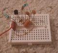
I simulated an oscillator in Falstad and i was very happy with its performance. What i needed was a simple oscillator that could produce a sine wave with >300v p-p in the tank. This Oscillator seemed to simulate correctly, but when i built the circuit on a breadboard, it did not oscillate.
Can you see any major flaws that would render it useless?
Is it something external, for instance stray capacitances that stop it or something inherent in the design?
Thanks!
 

Attachments

Thread Starter

rbrakhya

Joined Jul 16, 2024
8
Welcome to AAC!

How about posting a schematic?

What do the ends of your self made inductor look like?
Thanks! Sorry for just posting the simulator link, please see the schematic below. The end of the inductor were scraped clean and i put solder on them to make sure they were not insulated.
circuit-20240721-0814.jpg
 

Thread Starter

rbrakhya

Joined Jul 16, 2024
8
That 47 of capacitor looks “kind of” small. Try putting .001 uf capacitor across it and see if that fixes it.
Thank you for your reply! The 47p is what determins the oscillation frequency, the larger 2.2nF hardly effects it at all. The ratio between the 47p and the 2.2nF controls the feedback as i understood it. I will try it to see if it oscillates with 10nF across it anyway. Thanks!
 

Thread Starter

rbrakhya

Joined Jul 16, 2024
8
I only see one wire coming off the breadboard. How's does it get power and how do you get >300v p-p?
Sorry about that. I did not have any black wire. The negative was connected between the larger caps, see edited image below. The 300v were what the simulator showed after the tank had fully swung up. I want to belive i can get high enough Q in the tank to get to a much higher voltage than Vcc at least. I have been playing with small loop antennas and thought that the funny-looking tank circuit of this schematic kind of resembles a small loop antenna with its minimal L and high C and a tapping point for the feed (although i now realize loops are usually fed on with a tapped inductor or separate coil).
Oscillator.jpg
 

BobTPH

Joined Jun 5, 2013
11,463
The transistor bias point depends on the beta, Perhaps the simulator has a different beta than your actual transistor.
 

Thread Starter

rbrakhya

Joined Jul 16, 2024
8
Thank you, you are probably right about that, but i need the high voltage in the tank as i want to try to do some dielectric heating. I want to make the load a part of the capacitor (in paralell with the smallest one of the tank capacitors as it sees the biggest voltage swing). Adjusting the value on the smallest capacitor, from 47 to 10nF as you suggested did start oscillation (thank you!) with the transistor i am using, simulated in LTSpice with the BC547B transistor the circuit oscillates even down to 100p on this capacitor. This gave the high swing i am looking for. I have not modified the physical circuit yet.Workign.jpg
 

Thread Starter

rbrakhya

Joined Jul 16, 2024
8
What is the intended frequency? I see lots of oscillation , but 750 NANOHENRY is not much inductance. What frequency is the goal???
I intentionally kept the inductance low to be able to increase the capacitance as much as possible for a given frequency. I need the smallest capacitor to be as large as possible compared to the load capacitance so that the frequency doesn't change much with changes in the load capacitance. I expect the load to be in the order of 5pF. I was thinking of using a thick 3mm copper inductor with 5-6 turns to keep Q high, and also use a high Q cap as c1. Do you think that the circui may be too low Q to oscillate with this transistors gain? The frequency is not very important, but i would like to keep it with ism 27Mhz or 13Mhz to as an interference mitigation. Preferably 27Mhz as the band is much wider and the delivered power would be greater for a given current.
Skärmbild 2024-07-28 212336.jpg
 

MisterBill2

Joined Jan 23, 2018
27,164
In the circuit shown in post #7 I see a diode between base and emitter. THAT is universally a poor choice, no matter what. I see it in no other instances. Was it just an error?? With the low sweep rate we are not able to see the waveform, making the display rather useless. With most oscillators, rapid starting is not as important as frequency stability.
 
Top