Yet another 1 transistor FM circuit (experimental)

Thread Starter

ci139

Joined Jul 11, 2016
1,898
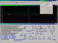
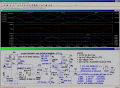
Well - the point is - that i have no scope nor a frequency counter (i don't do anything radio usually)
I have redesigned this circuit 2 times to bigger power draw/use (this one the largest - not yet built)
So - as the previous v.-s didn't started up (used 170nH || 7.5pF (double 15pF in series)) then if you
can see there anything i should know (the simulator does not) e.g.
?1? -- the critical caps. to trim,
?2? -- the bandwith and stability - is this circuit to pollute FM-band
?3? -- the PCB ? anything to connect to single points , single double layer
?4? -- anything to redesign ? power draw ? can the std. linear regulator be used as a power source
?4.1? -- inductive filters to supply (the Henry range ? should/could it be as mains line filter - a TF - for PWM PSU-s)

actually i need some inter robot data link (custom, non-commercial) in future - just thought i test this one out first

you shouldn't feel responsible to answere all questions - if i get 1 answer that helps it forward then it's very good
 

Attachments

Thread Starter

ci139

Joined Jul 11, 2016
1,898
since i needed this thing to work i started with modified src.

i don't have a frequency counter but 2 of my stereos actually do - so . . .
* -- the transmission power actually worse than the very first 1 i built (not shown anywhere here)
* -- but the frequency stability is almost excellent !!! (but the sub noise of it was heard many places over the FM band - 3 places ??)
* -- applies to attachments
 

Attachments

DickCappels

Joined Aug 21, 2008
10,152
I intentionally designed that to be very low power so it would not cause interference and so that it could get long life from a single AA cell. It was sometimes used with a little FM receiver that you could plug into your ear -that was 2002 as a poor man's substitute for Bluetooth.

Most likely reason you can hear it on multiple spots on the dial is because your receiver has "images" (sees the signal in the wrong place because of limitation of filtering or a dirty local oscillator). This is especially likely if your tuner is synthesized.

If you want more power out, drop that 330 ohm resistor to something like 47 ohms and raise the battery voltage to something higher, like 6V to 12V.
 

Thread Starter

ci139

Joined Jul 11, 2016
1,898
you can hear it on multiple spots
actually i can't hear it but likely the AAA powered MP3 player's some sort of internal clockworks - near the bottom , center and **top of the FM band - the audio comes through at 1 "station" only just higher the top**

i still have problems in realizing how your circuit works • the resonant coil - if you wind it from #22 (=5·10^-3·92^((36-22-4)/39)·25.4=0.6478mm)
tight over Ø5mm you get 250nH if self interleaved over Ø3.7mm (outside diameter 5mm) you get apx. 100nH inductor -- the ®schematic does not mention the transmition frequency nor other operationals . . .


if the 100kΩ is correct then i assume the oscillator works somehow on "capacitive buffer" enabled dynamic DC - that the Spice won't even consider starting any oscillations on ?

i intentionally mounted the antenna to E through a small cap. so it would be easier to find the tune point for the circuit - as i don't yet grasp the circuit i can't tell whether it requires higher power to extend the reception distance or not

ha! , by the way - an interesting picture about Hi-Fq. wire inductance


the less the Ø (the more the AWG #) - the greater the inductance

( (( chinggg )) )
Test BJT 002-03-180-fw-F3std_(R)Test-v_02.png
(>!perhaps!<)
 

Attachments

Last edited:

DickCappels

Joined Aug 21, 2008
10,152
The SPICE circuit you posed in post #4 is unlikely to work unless L6 and C3 are tuned to oscillation frequency. Most people just run a capacitor from the base to ground.

It is a Colpitts oscillator. You tune it by stretching or compressing the inductor.

Good point about the 100k -if you increase power, the 100k should be lowered as well as the other measures recommended.

Whomever copied the web page did not do a very good job because most of the text was left out of the bootleg version (as was the copyright notice!). The original web page is here
 

radiohead

Joined May 28, 2009
514
Compressing or expanding the coil is a technique for rough tuning a basic colpitts oscillator. You should replace the 18pF capacitor in the tank circuit with a 5-30pF trimmer cap (any will do) for fine tuning. Use a plastic implement to reduce drift... it will still drift though.

I would advise using a 9-volt battery fed through an LM7805 +5 volt regulator to keep the voltage steady... again, an attempt to increase stability. This circuit frequency will drift as the battery dies, so try to keep your voltage steady.

Look at the datasheet for the 2N4401. http://www.datasheetcatalog.com/datasheets_pdf/2/N/4/4/2N4401.shtml Will 1.5VDC through a 100K resistor allow enough voltage to bias the transistor base??

Just because you don't hear it, doesn't mean it is not transmitting. If you don't have a wideband receiver, you have to try to get the center frequency within the standard FM band in order to hear it.
 
Top