Facebook
 Google
 GitHub
 Linkedin
Hi all,
I have interested in IoT projects and exploring this subject as a basis to learn electronics.
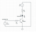
I am currently trying to create a learning remote control circuit (see attached schematic) but my electronics experience is novice and although I have recently acquired a basic understanding of ohms law and am able to apply this to simple circuits I am a little confused with base resistor values when including the 2N2222 npn transistor and how one would choose the ballast resistor as (if I understand correctly?) I think the 2n2222 can act as an amplifier that amplifies the current through the collector and emitter. which further confuses me about how to size the ballast resistor.
I would like the TSAL6400 IR LED to run as bright as possible within the confines of the current definitions in the spec sheet.
Looking at the spec sheet it specifies that the TSAL6400 has a forward current of 100mA. But I have read in various places that this may be specifying a continuous on state and that IR LEDs may be able to operate happily at higher current levels if they are to be pulsed, like in a remote control application. The other current definitions in the spec sheet are peak forward current 200mA and surge forward current 1.5A. The spec sheet also displays Forward Voltage @ 100mA to be 1.35V (typical) and 1.6V(max). Also it specifies Forward Voltage @ 1A to be 2.2V(typical) and 3V (max) but I don't understand whether that implies that the TSAL6400 can operate at such high amperage if pulsed.
I think the above should be enough information to work out the resistors in the circuit but I don't know enough to be able to interpret these values and apply them tor my application and was hoping that someone might shed some light on how I would approach this?
Many thanks in advance.
Robert
I have interested in IoT projects and exploring this subject as a basis to learn electronics.
I am currently trying to create a learning remote control circuit (see attached schematic) but my electronics experience is novice and although I have recently acquired a basic understanding of ohms law and am able to apply this to simple circuits I am a little confused with base resistor values when including the 2N2222 npn transistor and how one would choose the ballast resistor as (if I understand correctly?) I think the 2n2222 can act as an amplifier that amplifies the current through the collector and emitter. which further confuses me about how to size the ballast resistor.
I would like the TSAL6400 IR LED to run as bright as possible within the confines of the current definitions in the spec sheet.
Looking at the spec sheet it specifies that the TSAL6400 has a forward current of 100mA. But I have read in various places that this may be specifying a continuous on state and that IR LEDs may be able to operate happily at higher current levels if they are to be pulsed, like in a remote control application. The other current definitions in the spec sheet are peak forward current 200mA and surge forward current 1.5A. The spec sheet also displays Forward Voltage @ 100mA to be 1.35V (typical) and 1.6V(max). Also it specifies Forward Voltage @ 1A to be 2.2V(typical) and 3V (max) but I don't understand whether that implies that the TSAL6400 can operate at such high amperage if pulsed.
I think the above should be enough information to work out the resistors in the circuit but I don't know enough to be able to interpret these values and apply them tor my application and was hoping that someone might shed some light on how I would approach this?
Many thanks in advance.
Robert
Attachments
-
 14.3 KB Views: 26


")