 Facebook
 Google
 GitHub
 Linkedin
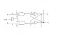
I am unable to understand the working of a positive edge triggered JK flip flop. In the figure, there are 2 AND gates on the left (one over the other) and there are 2 NOR gates on the right (one over the other). I have used an RS flip flop to construct the JK flip flop. The inputs J and K are denoted as 2 & 5 respectively. Q is the complement of Q. The output Q is connected to input number 1 of upper AND gate and the output Q is connected to input number 6. The inputs 3 & 4 are connected to the clock pulse.
Now consider the input condition J=0, K=1 and at this point the clock pulse makes a positive transition. The explanation given in my book is as follows:
When J is low and K is high, the upper AND gate is disabled, so there is no way to set the flip flop. The only possibility is reset. When Q is high, the lower gate passes a reset pulse as soon as the next clock edge arrives. This forces Q to become low. Therefore, J=0, K=1 means that the next positive transition of the clock resets the flip flop.
The lower gate sends a reset pulse which means it sends a low voltage signal. Why does this happen? Now, the lower AND gate has 3 inputs. At the time the positive edge of clock pulse arrives, K=1. So, two of the inputs of the lower AND gate is high. Suppose at this instant, Q was high. Then three of the inputs of the lower AND gate is high, which means the output would be high .i.e. S is high. A high at any of the inputs of a NOR gate gives a low output. Hence Q is low. Now, Q is one of the inputs of the upper NOR gate. As J=0, R=0. Hence the two inputs of the upper NOR gate is low. Hence, Q=1. There is something to do with the third input(1 & 6). I think digital electronics is tough if you dont have good teacher. Someone please guide me!!!!!!!!!!!
Attachments
-
 9 KB Views: 65


