 Facebook
 Google
 GitHub
 Linkedin
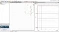
Can these LC circuits also run in real life and generate radio waves or I am doing something wrong ?
Circuit A : http://tinyurl.com/yayhfljx
Circuit B : http://tinyurl.com/y7z5uhqc
Circuit A : http://tinyurl.com/yayhfljx
Circuit B : http://tinyurl.com/y7z5uhqc
Last edited:

 ?
?


