Wiring Up Motor (repurposed) Single Phase 120V with centripetal switch and relay

Thread Starter

Willjovi

Joined Oct 7, 2024
10
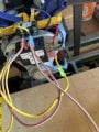
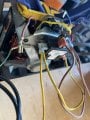
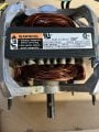
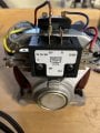
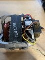
Hello, I have this motor that I took from a trash compactor to give it new life. It is a 1/3 hp 115/60 v/hz Model S58NXMJH-6657 6.6Amp. It has a centripetal switch 777971 that was used with the original compactor and a relay 0344 T-0-D 20MAALGA 018. Like a dufus, I tossed the schematic, so I am just working with what I have.

Measured the resistances through the different wires:
Gray/Red 5.8 Ohms
Blue1/Blue2 1.0 Ohms
Blue1/Yellow 2.9 Ohms
Blue2/Yellow 2.9 Ohms
Brown/Gray 3.4 Ohms
Brown/Red 3.3 Ohms

It is my understanding that the high resistance wires are the start windings as the compactor did not come with a start capacitor.

Questions:
1. what do I connect across the relay (which color wires)?
2. based on the resistances and pictures, can you help me to wire the switch up? My guess is that red/gray go to the O/BK and W OR BK on the switch as those start connected and then when the centripetal switch spins up, those go to open.

Any help is much appreciated.
~William
 

Attachments

MaxHeadRoom

Joined Jul 18, 2013
30,557
I believe those connections on the rear unit is for the automatic reversing mechanism, when the pressure builds and loads the motor the switch is operated for reverse/
 

Thread Starter

Willjovi

Joined Oct 7, 2024
10
I believe those connections on the rear unit is for the automatic reversing mechanism, when the pressure builds and loads the motor the switch is operated for reverse/
Thank you for your reply. I wasn't sure if it was essential that I keep it or if I could toss it in a bin and bypass it to get the motor running. I don't plan to use it to reverse the direction, so if I understand you correctly, I don't need to keep it in the circuit at this point.
 

MisterBill2

Joined Jan 23, 2018
27,159
OK, a cheating trick will be to search out a service manual for the compactor that has a manual or a service schematic. Even more important is that you learned the value of schematic diagrams.
 

Thread Starter

Willjovi

Joined Oct 7, 2024
10
Here is the compactor with the centripetal switch replacement procedure.

Below is a schematic for a compactor that could be similar. Based on this schematic, it would be red/gray for the start winding/centripetal switch and then blue/yellow for the main? and if I have 2 blue wires, do I put it to either as there is only 1 ohm resistance across them?compactor schematic.jpg
 

Thread Starter

Willjovi

Joined Oct 7, 2024
10
Okay, I made some progress, got it to start up and run, but now I have a spare brown and blue wire. Will upload picture shortly of current configuration.
 

MaxHeadRoom

Joined Jul 18, 2013
30,557
Are you sure it does not act by the rotor being forced backwards and operating the Switch when it reaches max pressure when it is forced to stopwhen compacting?
 

Thread Starter

Willjovi

Joined Oct 7, 2024
10
Are you sure it does not act by the rotor being forced backwards and operating the Switch when it reaches max pressure when it is forced to stop when compacting?
Yes. I was able to wind a string and pull-start the motor, but otherwise, it just humms. I think the switch may be bad.

Here is how it is currently wired.

The switch is supposed to be closed between the O/BK and W or BK terminals at start and opens once the centripetal switch triggers.
 

Attachments

Thread Starter

Willjovi

Joined Oct 7, 2024
10
Update, the switch contactor at "O/Bk" was not making contact (was flipped backwards). Fixed that and plugged it in and now it works. So... what do I do with the leftover wires (Blue and Brown)? Do I just tape them off?
 

Thread Starter

Willjovi

Joined Oct 7, 2024
10
Measure the resistance from those wires to the others, and also between the two. In some areas blue and brown are mains power colors.
Measured the resistances through the different wires:
Gray/Red 5.8 Ohms
Blue1/Blue2 1.0 Ohms
Blue1/Yellow 2.9 Ohms
Blue2/Yellow 2.9 Ohms
Brown/Gray 3.4 Ohms
Brown/Red 3.3 Ohms
 

MisterBill2

Joined Jan 23, 2018
27,159
From the photo it became clear that the wires in question had non-insulated terminals, and tat they were short. Similar lengths with the other wires that go to terminals on that unknown black module. So it was an informed guess.
 
Top