wiring up a Regulator 12v to 5v for a USB connection

Thread Starter

spike1947

Joined Feb 4, 2016
496
Hi
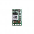
I am wanting to put a USB in my dash to power my DashCam , have seen a board that I can adapt to fit a female USB A socket , question is although this might look obvious , but were do I solder the 12v supply connector and the 5v output connector leads.

Am assuming that the IN+ is the 12v positive feed and the VO+ and GND are the 5v load , not sure what EN means , and how do I select the 5v feed .
as I said prob is easy , but maybe not got my brain hat on today .

cheers

Spike
 

Attachments

Thread Starter

spike1947

Joined Feb 4, 2016
496
Is that all the info you have for the board?
Where did you get it?
Hi

It is from ebay .

Supply Voltage: DC 4.5-24V
Operating Temperature: -40 to +85C
Conversion Direction: Step-Down
Type: Voltage Regulator
Current Conversion: DC to DC
1.Input Voltage: DC 4.5-24V
2.Output Voltage :integration adjustable and fixed output,back side can choose fiexd output voltage
3.Adjustable Range: 0.8-17V,fixed voltage (1.8V 2.5V 3.3V 5V 9V 12V)
4.Output Current: 3A (max),actual testing input 12V output 1.5A
5.Transform Efficiency: 97.5%(max) (6.5 to 5V 0.7A)
6.Switch Frequency: 500KHz
7.Output Ripple Wave: 20mV (12V to 5V 3A) 20m band width
8.Operating Voltage: -40 Celsius-85 Celsius
9.Output Overvoltage Protection: no
10.Static Current :0.85MA
11.Load Adjust Rate: ±1%
12.Voltage Adjust Rate: ±0.5%
13.Dynamic Response Speed: 5% 200uS
14.Output Short Circuit Protection: yes
15.Input Transposition Protection: no
16.Enable Control: yes
17.Connecting Type: soldering
18.Input Way: soldering
19.Output Way: soldering/pin
20.Soldering Hole Space: 2.54mm
 
Last edited by a moderator:

crutschow

Joined Mar 14, 2008
34,284
It would appear that you solder a small bare wire across the two 5V pads on the bottom to get 5V out (or bridge the two pads with a blob of solder).
 

cmartinez

Joined Jan 17, 2007
8,220
It would appear that you solder a small bare wire across the two 5V pads on the bottom to get 5V out (or bridge the two pads with a blob of solder).
Yes. And the ADJ pad would most likely activate the pot so that the output could be manually adjustable.
 
Last edited:

Alec_t

Joined Sep 17, 2013
14,280
But you likely don't want to use the ADJ and the fixed setting at the same time.
My eyes may be deceiving me, but from the reverse side of the pcb it looks as though the ADJ pot would be permanently in circuit unless that tiny trace near the right-hand end of the board were cut through?
 

cmartinez

Joined Jan 17, 2007
8,220
My eyes may be deceiving me, but from the reverse side of the pcb it looks as though the ADJ pot would be permanently in circuit unless that tiny trace near the right-hand end of the board were cut through?
It seems that your eyes are on to something. Perhaps the module has the pot enabled by default? And maybe one has to cut through that trace to enable the other options, as you're saying.
 

crutschow

Joined Mar 14, 2008
34,284
Yes, a trace connecting the two pads is clearly visible, so it would appear you need to cut that trace if you want to short one of the other pad-pairs for a fixed voltage output.
upload_2019-8-14_15-10-22.png
 

cmartinez

Joined Jan 17, 2007
8,220
Yes, a trace connecting the two pads is clearly visible, so it would appear you need to cut that trace if you want to short one of the other pad-pairs for a fixed voltage output.
View attachment 183928
Or maybe... shorting the other pads would determine the maximum voltage that could be reached when adjusting the trimpot? ... I guess the only way to know will be by trial and error.
 

Alec_t

Joined Sep 17, 2013
14,280
Agreed. On the one hand it's possible the pot is intended to be permanently connected, for use as a limiter or fine trimmer in parallel with a fixed resistor when any fixed voltage is selected. On the other hand, why are there two tinned pads for ADJ? Perhaps in case you change your mind having cut the trace :) ?
 

Thread Starter

spike1947

Joined Feb 4, 2016
496
Yes, a trace connecting the two pads is clearly visible, so it would appear you need to cut that trace if you want to short one of the other pad-pairs for a fixed voltage output.
View attachment 183928
Hi
Thanks for your answer .

Would I solder a lead to each VO+ and GND for the 12v feed and to solder a lead across the 2 pads next to the 5v and lead to IN+ for the other 5v outlet ! .but not cut any trace ! .
cheers
Spike
 

cmartinez

Joined Jan 17, 2007
8,220
That board seems to be based on a single chip. Are you able to see if it has any markings, and if so, what they are? Tons of things could be learned by looking at its datasheet.
 

Alec_t

Joined Sep 17, 2013
14,280
Would I solder a lead to each VO+ and GND for the 12v feed
No. As I see it:
The 12V feed goes to IN+ and GND.
The output is taken from VO+ and GND.
5V is selected by shorting the two pads next to the '5V' marking.

Its possible the EN input is already biased to enable the supply to work by default. If so it can be left floating.
Apply the 12V input and see what you get from the output. If zero, then the EN input would likely need shorting to IN+ or GND. Toss a coin and wait for the appearance of the magic smoke :).
 

cmartinez

Joined Jan 17, 2007
8,220
Toss a coin and wait for the appearance of the magic smoke :)
Whenever I try an unknown circuit for the first time, I always place my finger while powering it up on the component most likely to blow if something goes wrong. That way I can feel if it's quickly warming up and disconnect it before permanent damage happens.
 

djsfantasi

Joined Apr 11, 2010
9,156
I’ve used a board very similar to the one shown but I can’t confirm that it’s the same.

As I remember on the one that I had, this is how I wired it;
  • IN+ and GND are the input voltage.
  • VO+ and GND are the output voltage.
  • Short the two pads corresponding to the desired output voltage.
  • The ADJ trace is cut to enable setting a variable voltage; don’t bridge any other pads
  • Sorry, but I don’t remember if EN is active high or low.
Where did you buy this from? Do you have a link to the product description on the page from where it was purchased? That might be very helpful.
 

Alec_t

Joined Sep 17, 2013
14,280
I came across that pic too. Seems to be exactly the same board. Unfortunately the EN input gets no mention. Don't you just love Chinese non-datasheets :).
 
Top