Wiring an LED indicator lamp with a 16vac bell transformer

crutschow

Joined Mar 14, 2008
38,668
why one of these two circuits results in "hogging" and the other does not (assuming that the two LEDs drop different voltages).
In the top circuit each LED is totally independent of the other, since each has its own resistor directly to the power supply.
Thus what one LED does had no effect on the other (assuming the power supply voltage is independent of the LED currents).

In the bottom circuit the two LEDs are in parallel with one resistor in series to the power supply, so now what one LED does affects the other.
So, for example, if the normal operating voltage of one LED is 3V across it, and the other is 2V, the voltage across both LEDs will be 2V.
Since the 2V LED prevents the voltage from going to 3V, the 2V LED will hog all the current, burning brightly, while the 3V LED stays off.

Make sense?
 

crutschow

Joined Mar 14, 2008
38,668
Now, I'm curious why different colored LEDs drop different voltages.
It's generally related to the energy of the light color emitted.
The photon energy of shorter wavelength light, such as blue, is higher than longer wavelength light, such as red, so the LED material for blue must have a higher bandgap then for red, since the bandgap energy is basically what determines the frequency of the emitted light.
As you might expect, the higher bandgap material requires a higher voltage drop before it conducts current (to generate the higher photon energy), hence the difference in forward voltage drop for different color LEDs.
 

Thread Starter

camner

Joined Jul 3, 2017
20
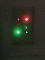
So, I finally got the parts and built the circuit. I used 24v LEDs rated AC/DC, so I didn't bother with any resistors or diodes. The 16vac transformer more than adequately powers the LEDs. The circuit works as expected, with one exception. As one can see in the attached photo of the LEDs, the lamps that are not supposed to be lit glow slightly.
IMG_1321.jpg

Before connecting the switches, I measured the resistance using a VOM and the switches in the open position show infinite resistance (at least the sensitivity of my VOM).

So, what is going on? Why is there some voltage "bleed" occurring that is partially energizing the lamps that are supposed to be off? And, more the point, what do I do about it?

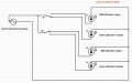
The circuit I used is below:
garage-door-as-built.jpg
 

marcf

Joined Dec 29, 2014
300
How long is the wire run?

How closely are the conductors to each other?

Super Bright LEDS can emit photons using a very low current.

I have one connected in series with a 10K resistor with 3.3v applied.

It is quite visible.
 

Thread Starter

camner

Joined Jul 3, 2017
20
Wire run is about 50 feet total (20 ft from transformer to LED, 30 ft from transformer to switches). 18/5 thermostat wire, so the individual conductors are quite close together (and aren't twisted).
 
Top