WIRING A SINGLE PHASE MOTOR - PLEASE HELP

Thread Starter

Johnnie Telfer

Joined Feb 27, 2015
7
Dear all

I'm struggling in vain to wire up my bi-directional single-phase tyre machine motor - despite a reasonable knowledge of engineering I'm just stuck, can't do it, admitting defeat on this occasion.

Please help me!

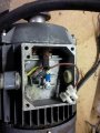
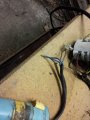
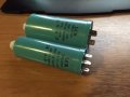
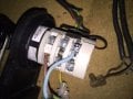
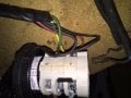
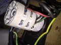
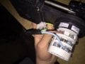
The motor is 4-pole, having 4 wires emerg from the windings (2 red and 2 black), with a couple motor-run (?) capacitors 25uF (MR25/440) and 10uF (MR10/400) connected in parallel (?) interrupting one of the red wires. Please see pictures

The motor says 40uF on it, and as one of the capacitors wasn't getting warm my friend said to change it, so now I've bought a 10 and a 30 and connected in parallel that gives me 40uF, the same as it says on the motor's data plate.

Will someone explain what I need to do with this motor to wire it up? The switch which is operated by a foot switch, bi-directional, surely switches the phase-shift one way or the other, but I need some help - it's probably nothing to one of you guys but I'm stuck.

I would whole-heartedly appreciate a quick response as I need my machine back up and running ASAP (for switching my spare tyre for one which is currently on the car).

Many thanks

Jonathan

I'm more than happy to advise on any boiler issues (Gas Safe man I am, not an electrical engineer as I'm now fully aware :)
 

MaxHeadRoom

Joined Jul 18, 2013
28,619
Don't see any pic's?
If these caps are in fact both motor run caps and were originally in parallel, then it appears you have identified the red pair as the start/run winding.
The red pair have the caps in series, so you need to swap the main winding pair with the cap/winding pair to reverse the motor.
How come the wiring was changed if you just replaced the caps?
What was the original problem, apart from the 'Cap not getting warm'?
Max.
 

Thread Starter

Johnnie Telfer

Joined Feb 27, 2015
7
I've now posted some pictures as I hope you can see?

I think that the original switch was burnt out a bit so I bought a new one (at about £100) and I left it stripped down too long and can't remember how to wire it back up!

Typical :)

How's Canada?

My grandfather was from Vancouver - I can't wait to one day have a holiday over there!
 

MaxHeadRoom

Joined Jul 18, 2013
28,619
You need the switching diagram for the switch you have, as you can see from the motor plate, you need to connect U1-W2 & V1-U2 for one dir and swap to U1-V1 & W2-U2 for the other.
I originally hail from Oxford, BTW. ;)
Max.
 

Thread Starter

Johnnie Telfer

Joined Feb 27, 2015
7
Hi Max, Oxford hey, no wonder you understand this stuff! I don't see how it's possible to connect those different combinations with only 4 wires coming from the motor???

Please see switch I've got, with which I can add links etc to make it perform numerous combinations.
 

Attachments

MaxHeadRoom

Joined Jul 18, 2013
28,619
I don't see how it's possible to connect those different combinations with only 4 wires coming from the motor???
There is only 4 connection and two combinations.
In the absence of the manuf. spec, You need to write out or draw a logic diagram of the status of the contacts when in each position.
I am assuming it is a three position switch?
Max.
 

Thread Starter

Johnnie Telfer

Joined Feb 27, 2015
7
Thanks.

The switch is one direction / off / other direction.

Am in correct that the data plate on the motor says 40uF, and a 10 & a 30 in parallel give me the 40uf required?

and these are simply connected one side to the red entering the motor, other side to the blue leaving the motor?

If this is correct I just need to know what to connect at the switch end?

Is it black1 - phase, black2 - red1, red2 - phase

by phase i mean live or neutral.

thanks immensely :)

So, where in Canada - Nova Scotia, Vancouver, Montreal, Quebec?

I'm in London
 

Thread Starter

Johnnie Telfer

Joined Feb 27, 2015
7
from what i can gather looking at the last page on that document, the most simple electro-mechanical circuit:

In both directions I want live and neutral connected the same way around to the black run winding wires.

In one direction I want the live and neutral connected to the start winding (incorporating the capacitors in parallel) wires one way around, and in the other direction I want to flip which red wires the live and neutral are connected to.

This gives a lag or lead at the start winding to create a lag or lead on it? Is it a start winding or auxiliary winding? Considering it's alway in use (no centrifugal switch).

Thanks

J
 

MaxHeadRoom

Joined Jul 18, 2013
28,619
If you imagine them as two different circuits connected across the supply, doesn't matter which is Live and Neutral.
One is the 'Main' winding, the other is a winding in series with a capacitor connected in parallel to the Main winding, to change direction you need to reverse one pair WRT the other.
If you connect up using the info on the plate, and get the switch to perform each connection, it will reverse.
Max.
So, where in Canada - Nova Scotia, Vancouver, Montreal, Quebec?
The Geographical centre of N.A.!;)
 

debe

Joined Sep 21, 2010
1,389
This is how I wired up a single phase motor on a Metal Lathe, which originaly had a 3 phase motor on it. This particular motor had a centrifugal switch in the start windings.Motor REV Switch.jpg
 
Top