Wine cooler

Pyrex

Joined Feb 16, 2022
502
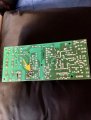
The board in the photograph is called SMPS. Switch Mode Power Supply.

This SMPS circuit is made so that the current passes through the thermistor (which is similar to a black disk), through one inductor, through a second inductor, and is fed into the diode rectifier. Then the rectified voltage charges two large black capacitors, which are connected in series.

Residues of soldering flux on the board will not harm its operation.
 

Thread Starter

Nvmarv

Joined Aug 27, 2025
21
I checked the 2 big cap on high side ..a little low on esr so I replaced and got a slight increase in voltage on low side from .3 to almost 1 volt was higher after I replaced one and tested but after testing the other( both about 100 uf under rating) but voltage went down slightly after replacing the second cap..around 1 to 1.2 volts
 

Thread Starter

Nvmarv

Joined Aug 27, 2025
21
What the the 2 yellow parts?.. diodes? And pic of clean up board and voltage on the transistor in middle is around 220v on right leg 0 and left is 0 as well the voltage on blue arrows are 0 and yellow is 230.. and it’s one of the transistors I replaced.. the red arrow is 0 volts.. both transistors are npn
 

Attachments

Last edited:

Pyrex

Joined Feb 16, 2022
502
The yellow rectangular components marked with an arrow are capacitors. They have only a slight effect on the operation of the SMPSo.
Check the voltage in DCV mode on the round black capacitors, one probe to the first pin, the second probe to the second capacitor pin.
If the voltage is close to zero, check the voltage in ACV mode on the first and second inductors; it should be around 230VAC.
 

Thread Starter

Nvmarv

Joined Aug 27, 2025
21
The yellow rectangular components marked with an arrow are capacitors. They have only a slight effect on the operation of the SMPSo.
Check the voltage in DCV mode on the round black capacitors, one probe to the first pin, the second probe to the second capacitor pin.
If the voltage is close to zero, check the voltage in ACV mode on the first and second inductors; it should be around 230VAC.
It measures 230 dcv first probe on first cap positive side second probe on neg on second cap both I recently replaced as they was low on esr meter..about 100 uf under
 

Pyrex

Joined Feb 16, 2022
502
You don't need to replace everything in a row, you first need to isolate out which components are faulty.

We are communicating in a technical forum, so you need to provide as much information as possible.
What type of transistors were those replaced?
What is the mains voltage in your region?

By all accounts, it seems like the fault is in the hot side.
Check all resistors and diodes with a multimeter, they do not need to be unsoldered from the PCB.
Low resistance resistors are prone to breaking or their resistance may increase abnormally.
When you are measuring the resistance of resistors on a PCB and suspect that their resistance is too high compared to the color code marked on them, unsolder the resistor and check again.
Of course, it is enough to solder only one resistor terminal.

Keep in mind that these are SMPS, and repairing them is not a very easy task.
 

Thread Starter

Nvmarv

Joined Aug 27, 2025
21
someone suggested testing the big caps and I did as they was high on esr meter..I’ve test all resisters on high side and all appear good. The transistors are a npn and before replaced tested bad..dcv voltage is 330v on most of high side except where it comes off the second cap and is around 165..the transister that’s connected to ground circuit has 330v on middle leg..165 on right and 0 volts on left which is connecting to ground
 

Thread Starter

Nvmarv

Joined Aug 27, 2025
21
Yellow arrow is pointing to the 2 nd transistors ( old pic) ..solder is better..clean and resoldered)voltage is 330 v in middle and around 165 on right and 0 on left ( bottom) of pic which is on ground( I also live in USA) so high side ac is 120 vac
 

Attachments

Last edited:

Pyrex

Joined Feb 16, 2022
502
You need to look for a schematic of this PCB, maybe you can find it on some forum.

As far as I could tell from the poor quality photos and the description, this SMPS is quite similar to an ATX type computer power supply.

If you can't find a real schematic, you can rely a little on a schematic from a similar ATX power supply unit.ATX power supply schematics can be found on the net.

Most ATX power supplies include a low-power pilot voltage converter. But this PCB doesn't seem to have a pilot voltage converter.
Therefore, you should probably follow the ATX power supply diagram without a pilot voltage converter .

https://danyk.cz/s_atx_en.html

I'm not sure if these schematics are correct. The first schematic is an ATX power supply without a pilot voltage converter.

If you want to continue the repair, you will need an oscilloscope at least
 

Thread Starter

Nvmarv

Joined Aug 27, 2025
21
You need to look for a schematic of this PCB, maybe you can find it on some forum.

As far as I could tell from the poor quality photos and the description, this SMPS is quite similar to an ATX type computer power supply.

If you can't find a real schematic, you can rely a little on a schematic from a similar ATX power supply unit.ATX power supply schematics can be found on the net.

Most ATX power supplies include a low-power pilot voltage converter. But this PCB doesn't seem to have a pilot voltage converter.
Therefore, you should probably follow the ATX power supply diagram without a pilot voltage converter .

https://danyk.cz/s_atx_en.html

I'm not sure if these schematics are correct. The first schematic is an ATX power supply without a pilot voltage converter.

If you want to continue the repair, you will need an oscilloscope at least
Ok.. tks for input I’ll do more research.. I’ve fixed several power supplies but mos
 

Pyrex

Joined Feb 16, 2022
502
Yes, I agree that electrolytic capacitors often fail in SMPSs.

And one more thing. If it's an SMPS without a small power pilot inverter, it probably won't produce output voltage if it doesn't have enough load on the output.

By the way, why are there so many cables connected on that PCB, what do they power or what other function do they perform?

Does your wine cooler have any other electronics besides this PCB?

I haven't had to repair a single wine cooler myself.
 

Thread Starter

Nvmarv

Joined Aug 27, 2025
21
it has several fans and a temp controller inside..it has 2 diodes to convert ac to dc voltage for inverter
 

wayneh

Joined Sep 9, 2010
18,104
By the way, why are there so many cables connected on that PCB, what do they power or what other function do they perform?
I'll probably forget something but they have: AC power in, TEC power out, fan(s) power out, thermistor, maybe an LED indicator out, and a connection to the display and control panel. I believe some units have more than one thermistor, one for the chamber and one on the TEC, so they can shut off the TEC if it's overheating.
 
Top