Facebook
 Google
 GitHub
 Linkedin
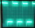
they were needed for it to work at all.So those were needed to suppress the noise/oscillations?
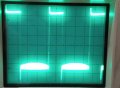
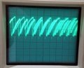
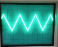
From what I can see it doesn't look symmetrical, noisey, and more of a sawtooth.How does the triangle wave look?
My breadboard isn't the best, I'm gong to redo parts of it.
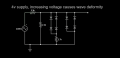
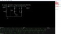
Here is the circuit I've bread boarded. Its shows 339's but on the breadboard I used 393's. I used 20K+1K for 21K (R6)

Last edited:


")