Facebook
 Google
 GitHub
 Linkedin
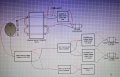
Hello, I am relatively inexperienced with electric circuits and am wondering if the attached circuit will work or if there is a better way to run the motors.
I had a similar setup and fried a raspberry Pi I believe caused by not having the reverse voltage connector when using the change over switch.
I don't know what effect the buck converters have on the rest of the circuit if any and I am unsure if the 24v capacitor is needed or setup correctly in the circuit. I would be grateful for any advise people can offer.