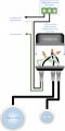
Does this circuit make sense?

Thread Starter

kenzo42

Joined Feb 26, 2014
48
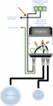
Newb question - this is a pool light that is controlled by a relay on a RP hat. The creator made this illustration. I am wondering if the black wire intersection (indicated by the red arrow) is correct? Shouldnt it be "not connected"? He's a very competent person, so I am questioning myself. Thank you.
129459225-553d6637-bd88-4bd3-a785-eadf00293979.png
 

WBahn

Joined Mar 31, 2012
32,990
It should not be connected.

Notice that the connection "dot" is only above the horizontal wire. This is probably meant to be the old style arc that "jumps over" the vertical wire. But because the wires are so thick, the arc needs to have a larger radius to make that clear.
 

Thread Starter

kenzo42

Joined Feb 26, 2014
48
It should not be connected.

Notice that the connection "dot" is only above the horizontal wire. This is probably meant to be the old style arc that "jumps over" the vertical wire. But because the wires are so thick, the arc needs to have a larger radius to make that clear.
That makes sense.
 

MisterBill2

Joined Jan 23, 2018
27,777
NO!! That should not be connected. THAT is a poor drawing in post #1, while the revision shown in post#4 is correct, and much more useful.
The terminal connection shown in post #1 is traditional in the trade, but the sequence for this application makes no difference. ( The "traditon in the trade" I mention is conecting the power source to the common relay terminal, in case there is a reason to also require power to the opposite relay terminal. )
Most folks are not aware of that tradition, which actually makes some sense in some instances. I saw it in southern Lousiana back in 1967. Oil rig eletricians.
 

schmitt trigger

Joined Jul 12, 2010
2,136
MrChips post is a perfect example of how a simple drawing modification, is the difference between a functional installation and a potentially dangerous one.
 

AnalogKid

Joined Aug 1, 2013
12,187
The erroneous connection dot notwithstanding, I prefer the connections in #1 over those in #4. The mains hot (Line) lead should go to the relay COM terminal, and NO terminal should go to the switched load. This way, when the relay is "off" and the NO-COM connection is supposed to be open, there is not mains voltage at the NO terminal.

ak
 

MrChips

Joined Oct 2, 2009
34,964
I had no real intentions to interchange NO and COM.
I drew it this way otherwise I would have had to draw a "jump over" as WBahn correctly identified.
 

WBahn

Joined Mar 31, 2012
32,990
The erroneous connection dot notwithstanding, I prefer the connections in #1 over those in #4. The mains hot (Line) lead should go to the relay COM terminal, and NO terminal should go to the switched load. This way, when the relay is "off" and the NO-COM connection is supposed to be open, there is not mains voltage at the NO terminal.

ak
On the other hand, when the relay is "off", there WILL be mains voltage at the NC terminal -- a terminal that is unused and just sitting there inviting something to touch it. With the mains going to NO, there will never be mains voltage on the unused terminal.

As with most things, pros and cons.
 

AnalogKid

Joined Aug 1, 2013
12,187
On the other hand, when the relay is "off", there WILL be mains voltage at the NC terminal
I knew someone would point out that . . .

True, but that terminal is clearly flagged as *Normally* (relay *not* activated / rest state) *Closed* (possibly connected to something electrically), and electronical-type-persons know what that means. It is the one you have to be careful with when things are "off". OTOH, the Normally Open terminal should be nominally less dangerous (your application may vary).

ak
 
Last edited:
Top