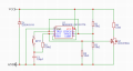
NE555 uses bipolar transistors that draw a fairly large current when the device switches. The result is the supply voltage will temporarily decrease which may or may not be a problem for the load. Adding a bypass capacitor provides an energy bank so the supply voltage won't drop nearly as much or at all. You can see the effect clearly with a scope.
By comparison, a CMOS TLC555 draws almost no current so there is almost no switching noise on the supply line. Therefore, a bypass capacitor provides less benefit but is still useful if the source impedance is large.
If you don't know the source impedance, I would use a bypass capacitor for either chip and definitely for the NE555.
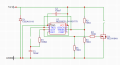
The source is a 12v car battery. I thought that a decoupling capacitor was maybe unnecessary because of this, besides that there are nu furder electronics on this board and no fast switching (just using the MOSFET as a switch)
Hi J,
When using a 12v car battery, I would recommend fitting an inline fuse, say 2Amp, for this application, in the positive lead as close as possible to the battery.
E
The answer to "does my circuit need a decoupling capacitor?" is always "Yes". We don't even need to know what sort of circuit it is: it will need a decoupling capacitor.
As another already stated, NE555 timer circuit is one of the worst offenders for injecting noise into power supply rails. CMOS versions such as LMC555 and TLC555 are low power devices and not as noisy.
The general rule for NE555 installations is a 0.1 μF at the IC power pins and 10 to 47 μF across the power rails.
Hi J,
The very low output impedance of a Lead Acid car battery will reduce the effect of any possible voltage spikes due to current draw spikes on the power rails.
If using say a 9V dry battery, [ high output impedance] both capacitors would be advisable
This is why I asked which voltage supply source was being used.
E
Just remember, wires have inductance. The very low impedance at DC can be much higher at AC (load switching edge frequencies) causing ringing/transients at the device load terminals side of the power wires. It seldom hurts to add a decoupling capacitor and most times, helps.
Using a decoupling capacitor is always a good idea.
The choice of using an AOD4148A might very well be high current and the signal is momentary.
Momentary and high current often use a big capacitor.
The source being a 12V car battery in years past was enough information, now cars have many electrical gadgets.
R6 load could be just about anything. One application might use a small mosfet and an automotive relay.
From a regulated logic into a bootstrap first is sometimes necessary, it depends on the application. AOD4184A_rev0_rohs.xls
Still some gate drivers using 555 are alright others are not. Things can happen when the lights, fan, wipers other accessories draw current
large capacitor like 470uF might reduce impact of intermittent voltage drops caused by other circuits.
Measuring current draw in simulation can be helpful. Automotive electric complexity is a challenge for a simple car battery.
Using a decoupling capacitor is always a good idea.
The choice of using an AOD4148A might very well be high current and the signal is momentary.
Momentary and high current often use a big capacitor.
The source being a 12V car battery in years past was enough information, now so many gadgets and things.
R6 load could be just about anything. One application might use a small mosfet and an automotive relay.
From a regulated logic into a bootstrap first is sometimes necessary, it depends on the application. AOD4184A_rev0_rohs.xls
Still some gate drivers using 555 are alright others are not. Things can happen when the lights, fan, wipers other accessories draw current
large capacitor like 470uF might reduce impact of intermittent voltage drops caused by other circuits.
Measuring current draw in simulation can be helpful. Automotive electric complexity is a challenge for a simple car battery.
Thanks for your input. But I don’t really understand what you are trying to say. The load that this circuit will be driving (R6) is a heating element for the steering wheel. This heating element draws around 3 amps. I thought that some voltage drop didn’t really matter because the 555 timer can work down to 4.5 volts, and a short voltage drop won’t really impact the performance of the heating element.
Do you agree with this, or do you think that the circuit won’t work? (I didn’t use a relay because space is limited.)
The PWM 3-A switching current to the heating element will produce more voltage spikes on the supply lines than the 555-timer itself. The purpose of power supply decoupling capacitors is two-fold, (1) to prevent a device from injecting noise into the supply line and (2) to prevent noise on the supply line from disrupting the operation of a device.
The reason for having this conversation is to remind circuit designers that it is better to take a proactive approach by applying proven best practices than waiting for the fault to happen later.
 Facebook
 Google
 GitHub
 Linkedin
 58.3 KB Views: 44