
I am trying to make a power wheel car remote controlled.
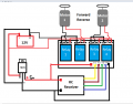
My setup is: I am using a 4 channel relay module to control the car's motor in forward reverse motion and the relay is getting the signal from a RC receiver. I have a 12V lead battery. The relay board and the receiver board needs 5v power so i used a 7805 IC for 12v-5v conversion but the 555dc motors are directly connected to the battery. So basically all the components are connected to same source.
Problem:
Every thing works fine if I don't connect the motors. all the relays turn on and off with the remote accordingly. And the output wires for the motors are also changing the polarity accordingly
But when i connect the motors and turn the relay on using the remote it turns on and off very fast, maybe 15-20 times a second or more.
At first i thought maybe the motors are drawing too much current or causing a voltage drop which is causing the relay module to shutdown. so just to check I used only one 5v dc toy car motor but still the same thing happens.
Also I used a laptop 19v charger instead of the battery for more voltage or current and it's same.
I haven't tried using capacitors for the regulator output as i don't have enough idea which one to use.
However when i use a separate 5v battery source for the relay and receiver then it works properly with both the laptop charger and 12v battery. so something is wrong with my main power source when i use only one source. How can i use the 12v battery for everything.
I have attached the diagram also.. plz i need help. Thanks for reading.
Attachments
-
 20.2 KB Views: 14


