Facebook
 Google
 GitHub
 Linkedin
Hey. I have been using a relay module which basically allows for a delay on/delay off function on the relay without the need of any microcontroller like a nano controlling it, hence making it pretty compact and easy to work with.
I have been using this module for quite some time now to mimic the coming/going home feature in modern cars where the car lights turn on for a couple of seconds after someone locks/unlocks their car to illuminate their path or what not. The relay module has positive and negative trigger terminals for it to initiate its task which in my case is to turn on the relay for 20seconds after the car is either locked or unlocked. Currently i am using the dome light as the trigger since that turns on/off when the car is locked/unlocked.
However, this is not the case in some older models where the dome light does not respond to the car locking/unlocking. What I have found though is that every car has two wires, one for locking and other for unlocking, running through which gives a pulse of negative trigger (is grounded) when the car is either locked/unlocked. these wires normally maintain 5v, dropping down to around 2.5v-2.7v when the car is in its sleep state aka the car has been locked for over 2-5minutes.
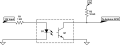
The question is how can i make use of this negative pulse where the wire gives a ground signal momentarily with the relay module when someone locks/unlocks their car. i would love to join the two wires with two diodes in between and connect these wires to the negative terminal of the trigger with the positive terminal connected to a constant 12v source so when the locking wires give a pulse of ground signal, the relay starts its function. However, connecting those wires to the negative terminal of the module would probably fry it as the two wires idle at 2.5-5v as described earlier and the module definitely does not have any protection if the polarities are swapped as it would be in this case.
Using a second relay to act as a trigger switch does not seem to be a viable option either to me. I'm pretty much out of ideas which is why i need your help.
If the answer was pretty simple and pretty much in front of my eyes, i do apologize in advance as i am an accounts student with a keen interest in crappy old cars lol. electrical stuff is still somewhat new to me even though i have been dabbing into basic automotive electrical stuff as somewhat of a hobby for a year almost. And yes, before you warn me, i take full precautions of everything and do not execute a project similar to this unless I'm 90% sure it wouldn't end up in an electrical fire")
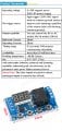
The module used:
https://a.co/d/9wrS5nd
I have been using this module for quite some time now to mimic the coming/going home feature in modern cars where the car lights turn on for a couple of seconds after someone locks/unlocks their car to illuminate their path or what not. The relay module has positive and negative trigger terminals for it to initiate its task which in my case is to turn on the relay for 20seconds after the car is either locked or unlocked. Currently i am using the dome light as the trigger since that turns on/off when the car is locked/unlocked.
However, this is not the case in some older models where the dome light does not respond to the car locking/unlocking. What I have found though is that every car has two wires, one for locking and other for unlocking, running through which gives a pulse of negative trigger (is grounded) when the car is either locked/unlocked. these wires normally maintain 5v, dropping down to around 2.5v-2.7v when the car is in its sleep state aka the car has been locked for over 2-5minutes.
The question is how can i make use of this negative pulse where the wire gives a ground signal momentarily with the relay module when someone locks/unlocks their car. i would love to join the two wires with two diodes in between and connect these wires to the negative terminal of the trigger with the positive terminal connected to a constant 12v source so when the locking wires give a pulse of ground signal, the relay starts its function. However, connecting those wires to the negative terminal of the module would probably fry it as the two wires idle at 2.5-5v as described earlier and the module definitely does not have any protection if the polarities are swapped as it would be in this case.
Using a second relay to act as a trigger switch does not seem to be a viable option either to me. I'm pretty much out of ideas which is why i need your help.
If the answer was pretty simple and pretty much in front of my eyes, i do apologize in advance as i am an accounts student with a keen interest in crappy old cars lol. electrical stuff is still somewhat new to me even though i have been dabbing into basic automotive electrical stuff as somewhat of a hobby for a year almost. And yes, before you warn me, i take full precautions of everything and do not execute a project similar to this unless I'm 90% sure it wouldn't end up in an electrical fire
The module used:
https://a.co/d/9wrS5nd
Last edited: