Why does this not work?

Thread Starter

luctem

Joined Aug 22, 2014
2
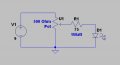
Hi all, I have made the following thing. The idea is to run a CCTV camera with 1 additional IR-LED.


Here is what i did. A transformer is plugged in the 240V. It outputs 9V, 1A. This goes to the wireless camera. This works! I actually split the main cables, with the idea to power the LED. Since i wasnt sure how much light i needed, i put a pod instead of the fixed resistor. The LED/pod work on its own. However, together the camera works, but the LED not.

Should this work?

PS. I might have burned through my LED at this stage....
 

djsfantasi

Joined Apr 11, 2010
9,155
I suspect too that you might have burned out the LED. LED's are current devices, and if the resistance value is too low, they will burn out. Quickly.

It would be better if you had identified the parameters of the LED (forward voltage drop and current requirements) and calculated the resistance needed.

If Vs is the supply voltage (9V in your diagram), and Vf is the forward voltage drop, and Iled is the LED current required, then the resistance can be calculated as follows:

(Vs - Vf)/ Iled = R
 

Thread Starter

luctem

Joined Aug 22, 2014
2
Aha, thing is that i only need to light a very small space and therefore did not know how big the resistor should be. If i have 9V and the LED is 1.2V 100mA, the resistor suitable would be 78R. Thing is... i probably need more than that since using the 80R resistor probably gives me too much light. Anyway, Good that you didnt say something obvious was wrong. Ill replace the LED (dont have one atm, otherwise i would have tried that straigth away) and see what happens.I guess i can 'dim' the light, then read the R with my multimeter...
 

MrChips

Joined Oct 2, 2009
30,621
How are you testing the IR LED? You cannot see IR with the eye.

As pointed out, you will burn out the LED when using a pot.
Use a fixed resistor such as 100Ω.
 

MikeML

Joined Oct 2, 2009
5,444
Here is how I would do it. Lets you dim the LED. If you turn the pot all the way full on, the resistor limits the current to less than 100mA (are you sure the LED will take that?)

You would likely do better with multiple LEDs, else you will have shadows. I use a visible camera borescope that has about 10 LEDs surrounding the camera lens to make the lighting more uniform.
 

Attachments

MrChips

Joined Oct 2, 2009
30,621
As ronv says, there is no need to ground the pot.
What you have shown is a voltage divider.
Remove the connection to ground and use the pot as a variable resistor.
 

MikeML

Joined Oct 2, 2009
5,444
As ronv says, there is no need to ground the pot.
What you have shown is a voltage divider.
Remove the connection to ground and use the pot as a variable resistor.
BS. I simulated it both ways. The LED intensity vs pot position is much more linear the way I posted it vs leaving the pot ungrounded. It also lets you turn the LED completely off, which cannot happen by leaving the third leg of the pot ungrounded...
 
Last edited:
Top