Why does Q12 and Q8 conduct current from base to emitter despite the resistors.

Alec_t

Joined Sep 17, 2013
15,101
Welcome to AAC!
"Why does Q12 and Q8 conduct current from base to emitter despite the resistors?"
Because the base voltage is higher than the emitter voltage. The resistors determine the amount of current.
Where is the +5V being applied?
 

Thread Starter

Willon

Joined Apr 26, 2025
7
Welcome to AAC!
"Why does Q12 and Q8 conduct current from base to emitter despite the resistors?"
Because the base voltage is higher than the emitter voltage. The resistors determine the amount of current.
Where is the +5V being applied?
The 5v comes from the far left , and how can i limit the voltage without affecting the rest of the circuit
 

Futurist

Joined Apr 8, 2025
721
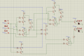
Iam using a 5V dc power source the same transistor works fine when disconnected from the rest of the circuit bur doesnt work like this advice is much appreciated
I see nothing on your diagram labelled IN1, IN2, Cin, OUT or COUT.

The diagram depicts two LEDSs, both RED.
 

AnalogKid

Joined Aug 1, 2013
12,043
the same transistor
Which one is that? Gold star for having reference designators in the schematic. Black dot for not using them in the text.

The #1 and #5 schematics are very hard to read. There are many lines going through the middle of components, so it is not clear at all where some connections are. Also, is the blue rectangle a signal loop that joins many components?

It looks like at least one signal goes through six base-emitter junctions and four resistors in series before getting to an LED that is grounded. That is way too many voltage drops for a 5 V circuit.

If possible, suppress or turn off the grid to improve readability.

Is there a reason you are not using logic gates for this?

ak
 
Last edited:

Thread Starter

Willon

Joined Apr 26, 2025
7
Which one is that? Gold star for having reference designators in the schematic. Black dot for not using them in the text.

The #1 and #5 schematics are very hard to read. There are many lines going through the middle of components, so it is not clear at all where some connections are. Also, is the blue rectangle a signal loop that joins many components?

It looks like at least one signal goes through six base-emitter junctions and four resistors in series before getting to an LED that is grounded. That is way too many voltage drops for a 5 V circuit.

If possible, suppress or turn off the grid to improve readability.

Is there a reason you are not using logic gates for this?

ak
By that transistor i meant Q7 and Q12(there has been a few chances so in the new schemathic its Q8 and Q12)

The blue line doesnt mean anything

I have attached a file thats hopefully easier to read

Im not using logic gates because it is a school project we need to use only transistors
 

AnalogKid

Joined Aug 1, 2013
12,043
If you redo the truth table in a more conventional manner, output condition patterns will be more clear. For example, across the top:

Cin 2in 1in | Out Cout

And columns with 000 at the bottom, increasing in a linear, binary sequence to 111 at the top.

ak
 
Last edited:

AnalogKid

Joined Aug 1, 2013
12,043
Consider this:

It looks like each pair of transistors functions as a logic gate; Q1 and Q2 form a NAND gate, Q7 and Q8 form an AND gate, etc. Look at your truth table. In a system with 16 possible outputs, there are only 4 that matter, two of those have the same input conditions, and the other two share two of three input conditions.. Do you really need 9 gates (or, more correctly, 18 gate inputs) to detect only two and one-half conditions?

ak
 
Last edited:

Thread Starter

Willon

Joined Apr 26, 2025
7
Consider this:

It looks like each pair of transistors functions as a logic gate; Q1 and Q2 form a NAND gate, Q7 and Q8 form an AND gate, etc. Look at your truth table. In a system with 16 possible outputs, there are only 4 that matter, two of those have the same input conditions, and the other two share two of three input conditions.. Do you really need 9 gates to detect only two and one-half conditions?

ak
If there is a better way to make a full adder with transistors i would definitely love to hear it
 
Top