That works too, but you're still cutting and shaping the copper. Sheet copper is already flat. All you have to do is cut it to the desired dimensions. You can even cut in some feet for soldering.
Indeed that was true a while back. It was a serious issue in a package I built in 1964, using 400PRV silicon diodes to replace a 6X4 rectifier tube. The fix was 100 ohm series resistors and a 0.01mfd shunt capacitor in addition to the regular filter cap.. But diodes are a lot better today, after 55 years, and so it would be adequate to look at the reverse recovery specs, both stored charge and recovery time.
The heat sink is for the forward loss power heating issue, quite different.
Better? Yes. More cost effective? I'm leaning toward "no". Solid copper could be overkill. The aluminum plate, though not explained, is likely first plated with nickel before plating the copper onto it. And I couldn't find anything that said what thickness the copper plating is. For the purpose of conducting electricity through the diodes, and for solderability, the aluminum plate with copper plating, I would guess, is going to be sufficient. And cheaper than a purely solid sheet of copper. Is solid copper better? I'm pretty certain it is.
There's a reason why you don't see copper heatsinks. Well, actually, yes, there are copper heatsinks; but I've never seen one glued on top of a CPU. Likely the key consideration is cost versus performance. Aluminum will be more cost effective than copper and will perform well enough. I say that - KNOWING - that I don't know what the thermal coefficient of each is in comparison to the other. I think aluminum is the better, but maybe the copper is. But again, good enough is - um - well - good enough.
Another option to get similar heat sinks is to get them off of the circuit board of a scrapped CRT monitor, or even a scrapped solid -state TV set of the CRT type. Heat sinks never go bad in any of those applications.
You seldom see copper heat sinks because they would be too expensive.
Copper has better thermal conductivity than aluminum. Copper = 413 W/m K, Aluminum = 237 W/m K. Don't ask me to explain the units, it gets pretty complex and I don't have the inclination to understand it.
The thickness of plated copper on a PCB isn't very thick. Wider traces will conduct more current than thinner ones will. The sheer surface area of the plated copper over the aluminum would support way more current than the leads of the diodes would. And in the picture I didn't see any thermal paste creating a thermal bridge between the diodes and the heatsink, if that's actually a heatsink.
Well, there you have it. Copper is better at conducting heat. But again, I fall back on "Good enough" is good enough. For what those diodes will see both in current and thermal dissipation, I believe the copper plated aluminum sheet will work just fine.
Given the options if I wanted to reproduce that heatsink I would just find some copper sheet material from a distributor like McMaster Carr Supply and if you want to be cool about it and make it like the picture just use some electroless nickel plate. Does the heat dissipation and heat conductivity factor really need to be greater than aluminum? All of this assumes roll your own rather than an off the shelf solution and the image with the diodes is not like they are using thermal past to conduct heat since we have round diodes on a flat plate. Looks like an epoxy resin on the diodes?
I'm not sure the metal plate is used primarily as a heatsink (even though I myself may have called it that for lack of another term)
There may be some heat transfer but I think they just used these plates to create the Diode H Bridge.
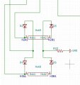
I think it is more of a conductive path. here is a schematic of their connection on the PCB.....
The exact same circuit is that if a 4 pin Bridge Rectifier.
I think they used this setup to get the ultra fast diode response time.
As you can see, the Kathode of Diode 2 and the Anode of Diode 3 are connected to the plate Hsk5. (soldered)
Likewise, D4 and D5 are soldered to the plate and to the PCB as illustrated.
A KBU1010 or similar packaged Bridge Rectifier would serve the same purpose, but would it be fast enough?
Interestingly, I could not get the recovery times for the packaged bridge rectifiers? The datasheet didn't list it. Odd.
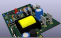
Here is a KiCAD 3D of the parts on the PCB
Notice I do not know how to make connections to the plates in KiCAD so I created vertical diodes and will actually solder the respective ends to the plate, not the PCB. I'm almost ready to send these PCB's to JCLPCB....and hope they work.
I did another version of this board with a 4 pin Bridge Rectifier rather than the 2 plates and 4 diodes.
It is never a wise choice to mount any power device so very close to the PCB for two reasons: First, it creates a lever effect if the device is ever bumped or pushed even a small amount, causing damage to the connection internal to the device. And Second, it assures that there will be some heat damage to the board material as time passes. This damage is far worse if there is a failure and the device burns up. I have seen holes burned in circuit boards that had charred material extending to almost a quarter of an inch around the part.
So there is a fair amount of heat that travels along the leads of the components. Having them up from the board also allows air flow that will provide some cooling.
It is never a wise choice to mount any power device so very close to the PCB for two reasons: First, it creates a lever effect if the device is ever bumped or pushed even a small amount, causing damage to the connection internal to the device. And Second, it assures that there will be some heat damage to the board material as time passes. This damage is far worse if there is a failure and the device burns up. I have seen holes burned in circuit boards that had charred material extending to almost a quarter of an inch around the part.
So there is a fair amount of heat that travels along the leads of the components. Having them up from the board also allows air flow that will provide some cooling.
This is not my design. I "wish" I was capable of designing something like this.
It is a DC to AC power inverter and was designed by the EE's at TrippLite
I've simply reproduced their circuit in KiCAD in order to get a replacement PCB....which I damaged in the repair process.
That said, can you be specific. Are you specifically referring to the Diode H Bridge?
What would you suggest as an alternative?
I see Bridge Rectifiers routinely mounted directly to PCB's in all kinds of devices so I'm not sure what you mean specifically in this case?

 Facebook
 Google
 GitHub
 Linkedin