What's the purpose of a joule thief?

Thread Starter

tjohnson

Joined Dec 23, 2014
611
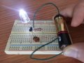
Back to the original topic, I finally got my joule thief circuit to work! I got a toroid from a dead CFL that I salvaged from the recycling bin at my local Home Depot. I couldn't find any magnet wire to wind it with, until I watched this video and learned that CFLs have some inside:

I also found this webpage helpful, which @Rolland B. Heiss linked to in his joule thief thread.

Many thanks to @Brownout for his persistent help! He gave me the idea to check at Home Depot for a dead CFL.

It would be nice to add a 0.1μF capacitor to lengthen the battery life, like @DickCappels suggests on his webpage, but I don't have one right now. I'm just happy to have gotten this to work.:cool:
 

Attachments

Thread Starter

tjohnson

Joined Dec 23, 2014
611
I have a question about the joule thief circuit that I made. The AA battery I'm using has 1.31V, and the LED in the circuit needs ~3V to light up. Now that I've gotten my circuit working, I was curious to measure the output voltage (at the LED), and was surprised to find that it read 1.26V. How can my joule thief be working if the output voltage is 0.05V less than the input voltage?o_O
 

Brownout

Joined Jan 10, 2012
2,390
I you're measuring the volage with a DMM, you're not seeing the higher "turn on" LED voltge. This is not a steady DC value, and thus you are measuring an average voltage, averaging turn-on and tun-off voltages. To get the "converted" turn-on voltage you'll need to viewit with an oscilloscope.
 

DickCappels

Joined Aug 21, 2008
10,661
One end of the inductor is connected to the battery and the other end of the inductor is connected to the collector of the transistor and the LED. DVMs on the DC scale tell you the average voltage. The average voltage across an ideal inductor is zero volts. But the LED must be getting more than 3 volts to light -and that tells us that there must be a peak voltage higher than the battery voltage.

To see the peak voltage you can use a diode peak detector.


Connect the "-" connection of the peak detector to ground and measure Vout with your DVM. Add 0.5 volts to account for voltage dropped across the diode.

The diode should be a fast small signal type like 1N914, 1N916, 1N4148, 1N5711, etc.

The capacitor should be a several microfarads.

You can probably measure the peak voltage by putting your DVM on an AC scale but that brings into question the bandwidth of the AC measurement circuitry and the conversion of the reading from "RMS" to peak.
 

Thread Starter

tjohnson

Joined Dec 23, 2014
611
You can probably measure the peak voltage by putting your DVM on an AC scale but that brings into question the bandwidth of the AC measurement circuitry and the conversion of the reading from "RMS" to peak.
Thanks for the detailed explanation. I tried measuring the AC voltage on my multimeter and got a reading of 0.9V, so that doesn't seem to work. I'll try using a diode peak detector if I have time.
 
Last edited:

takao21203

Joined Apr 28, 2012
3,702
One end of the inductor is connected to the battery and the other end of the inductor is connected to the collector of the transistor and the LED. DVMs on the DC scale tell you the average voltage. The average voltage across an ideal inductor is zero volts. But the LED must be getting more than 3 volts to light -and that tells us that there must be a peak voltage higher than the battery voltage.

To see the peak voltage you can use a diode peak detector.


Connect the "-" connection of the peak detector to ground and measure Vout with your DVM. Add 0.5 volts to account for voltage dropped across the diode.

The diode should be a fast small signal type like 1N914, 1N916, 1N4148, 1N5711, etc.

The capacitor should be a several microfarads.

You can probably measure the peak voltage by putting your DVM on an AC scale but that brings into question the bandwidth of the AC measurement circuitry and the conversion of the reading from "RMS" to peak.
could be 47nF if there is no load and frequency is high.

1n4148 is pretty good even for switcher ICs when you only need small currents.

There are two ways to connect LEDs, across the coil or across the inductor.
Across the transistor gives more brightness.

And rectification as seen above. The capacitor keeps energy from the previous cycle so the backwards induction will rise to higher voltage.

My circuit produces high voltage using a plain 2n3906, 100 volts from 2x AA batteries.
Both across the secondary out of the base, and one-pole only connecting something to the other end of the coil and holding it in your hand. Your body becomes the antenna!

Current is low, if you hold a LED, voltage drops down.

Its a very fast way to test LEDs. Just hold them touch the circuit with one pin.

Its not really a Joule Thief just very similar circuit.
Primary is added turns on off the shelf Panasonic inductor. Secondary connected to the base, and circuit is started with a pushbutton connecting the other end to ground. Transistor turns hot fast when using 2 cells! So the pushbutton shouldnt be hold down for a long time.

I was thinking its useless building these Joule Thiefs all over again, 20 times, 30, 50 times, you name it.

But I got high voltage using plain 2n3906, and very few parts, from 1x AA even for orange neon lamps.

The circuit actually is a flip flop as well.

Purpose of a Joule Thief? A starting point into electronics. You can learn a lot if you build it all over again and again.
 
Top