Facebook
 Google
 GitHub
 Linkedin
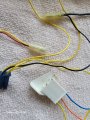
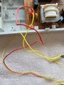
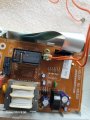
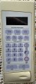
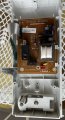
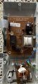
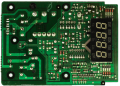
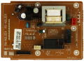
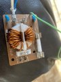
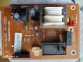
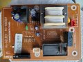
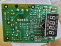
Is in possible to re-purpose this microwave control board to use it as a clock and create a timed recepticle? The attached is from a Samsung Microwave
Attachments
-
 115.2 KB Views: 26
 -
 184.8 KB Views: 25
 -
 160.9 KB Views: 24


.jpg")